More PIC Microcontrollers:In-Circuit Debugging and Power PICs

In-Circuit Debugging

Mid-range PIC chips are now generally being designed to support in-circuit debugging (ICD), where, after programming, the firmware can be executed within the final target hardware under control of the MPLAB IDE via the programming interface. This allows the application to be more fully tested using the same debugging tools available in MPSIM and makes it easier to

eliminate firmware and hardware bugs in the final stages of testing. Smaller chips, which do not provide internal ICD support, must be debugged using a header connector that carries a version of the chip that contains the ICD circuitry. The PICkitX development programmer provides all programming and debugging features we need at minimal cost, while the ICDX module may be needed to debug smaller chips which require a header.

Power PICs

To complete the analysis of the whole PIC range, the features of the more powerful PICs must be considered. The PIC24 series of microcontrollers have a 16-bit internal data bus and ALU, and move from the single working register model to a set 16 x 16 bit working registers. Otherwise, the architecture is similar to the 8-bit MCUs. The dsPIC30 and dsPIC33 are also 16-bit processors, but include a digital signal processing (DSP) engine for fast floating-point calculations. Top of the range are 32-bit PIC32 chips with the kind of central processing unit (CPU) enhancements used to improve performance in CISC devices such as the Intel® PC processors: a split-bus architecture, instruction pre-fetch and cache, five-stage execution pipeline and high-performance interrupt controller. The same MPLAB IDE supports the whole range, but these processors will normally be programmed in C, to make optimum use of the additional features.


More PIC Microcontrollers:Protection Devices,Interrupts,Hardware Timers and In-Circuit Programming

Protection Devices

Internal timers are used to ensure a reliable start-up on power-up, after a reset or a short-term dip in the supply voltage. In the 16F690, the power-up timer provides a nominal delay of 64 ms to allow the power supplies to stabilize before the program execution begins. The watchdog timer allows the chip to reset itself automatically if the program execution fails to follow the normal sequence, thereby improving overall reliability. Brownout protection allows the chip to reset in an orderly fashion if the power supply fails for a short period. Full details, including a block diagram, are provided in each chip data sheet. Over time, these protective features are becoming more elaborate, so that, if they are properly applied, the overall reliability of PIC applications is improved, at the expense of the firmware becoming more complex.

Interrupts

An interrupt is an internally or externally generated signal, which forces the processor to suspend the current operation and execute a interrupt service routine (ISR). The ISR thus has a higher priority than the background process. PIC chips provide a variety of interrupt sources, for example, a change on a selected input, or a hardware timer timeout. There is an interrupt priority system available in the more advanced 18 series PICs; this allows the chip to be set up to ignore an interrupt source if a more important one is already active. In CISC microprocessors, multiple interrupt vectors are usually available, and a different ISR can be invoked for different interrupt sources. In the PIC, all interrupts have to be serviced via the single interrupt vector, located at address 004 in program memory. To differentiate between them and to determine the action required, the ISR needs to check the relevant control register flags, to find out which interrupt source is active, before branching to the required routine. As the number of peripheral devices increases, such as additional timers, serial ports and so on, the number of potential interrupt sources increases, making interrupt servicing via a single vector more complicated.

Hardware Timers

The number of hardware timers available generally increases with the chip complexity. They are either 8-bit or 16-bit counters, with prescalers or postscalers, which divide down the input or output of the counter to extend its range. If we take the motor program in Chapter 11 as an

example, we can see how additional hardware timers could have been utilized; the 20 ms time interval and the motor output cycle delay could both have been implemented as hardware operations, while the sensor pulse monitoring could have used RB0 interrupt. As well as simple counting and timing, the hardware timers can be configured to measure input intervals, generate timed outputs and drive output loads using pulse width modulation (PWM; see Section 12.3.1 below). Sometimes, independent clocks are associated with the timers and protective devices, so that they can continue to function when the main clock fails, or a different timebase is needed.

Sleep Mode

This is useful for terminating programs that do not loop continuously, suspending operations pending an interrupt or saving power in battery applications. The processor switches off the clock and disables most of its normal functions when the instruction SLEEP is encountered, with current consumed dropping to around 1 mA, or less in low-power devices (LP designation). Using SLEEP to terminate a program prevents it continuing into unprogrammed memory locations. These default to all 1s, which generally corresponds to a valid instruction code, ADDLW FF in 14-bit code (W, C, DC and Z all affected). If a program is not terminated with a SLEEP or GOTO instruction, the program will carry on to the end of memory, the program counter will roll over to zero and the program will restart. A hardware reset input or suitable interrupt will be needed if the application code is terminated with SLEEP.

In-Circuit Programming

The PIC microcontrollers use a common program downloading system, which consists of transferring the machine code in serial form via one of the data pins when the chip is in programming mode. Previously, the chip would be placed in a programming unit for downloading the application code, and then physically transferred to the application board. Now, the chip is normally programmed in circuit, where the chip can be left in circuit, reducing the risk of damage. It can then be programmed after the circuit has been manufactured, and reprogrammed at any time, via a six-pin on-board connector, which can be seen in the 16F690- based LPC board.The connector can be in the form of a SIL (PICkit 2/3) or RJ-11 (ICD 2/3) connector (see Chapter 7).


More PIC Microcontrollers:EEPROM Data Memory and ALU and Working Registers

EEPROM Data Memory

This is useful in applications where data read in at the ports or produced by the processor needs to be stored in non-volatile memory. For example, in a keypad-operated electronic lock, the lock code is entered by the user and then retained to be checked against user keypad input to release the lock. Data logging applications, where sampled input data may need to be retained over a period of time, may also need to store the data while the power is off. Electrically erasable programmable read-only memory (EEPROM), unlike flash ROM, can be written as individual data bytes, but is not as physically compact, so is provided in smaller blocks. EEPROM capacity ranges between 256 and 1k bytes, and is not fitted in some chips.

ALU and Working Registers

CISC processors tend to have a block of registers for storing current data, rather than a single working register (W) as found in the PIC. They also tend to have much larger address spaces. This means that the instructions, including operands, are typically 4 bytes in total, often more, compared with 14 bits for the PIC 16. An architecture with only one working register, used in conjunction with the RAM register block, reduces the overall number and complexity of instructions required, as the options are reduced. This does mean, however, that all data transfers must go through W. In the more powerful MCUs, the arithmetic and logic unit (ALU) support hardware can be more elaborate. For example, the 18F4580 has an 8 x 8 multiplier, but still has only one working register.

Stack Size

The stack size determines the number of subroutine or interrupt levels that can be used in the application program. A CISC processor can have an unlimited stack, as general purpose RAM is used, unlike the PIC, which has a dedicated internal stack of limited depth. The 12 series chips have only a two-level stack, the 16 series eight levels, and the 18 series 32 levels. This reflects the typical program complexity for each type. The application programmer needs to be aware of this limitation, and balance the advantages of a well-structured program using multiple subroutine levels, and the absolute limit imposed by the stack size. Unlike in CISC processors, the stack cannot be overwritten by a program instruction, making it more secure.


More PIC Microcontrollers:Harvard Architecture and RISC Instruction Set

Harvard Architecture

In conventional processor systems, the instruction codes and associated operands have to be transferred from memory using the same address and data bus as the system data, that is, the data read in via inputs or generated by the processor. The PIC architecture has separate paths for the instructions and the system data. Therefore, the instruction fetch operation can be carried out at the same time as the results from the previous operation are stored. As a result, the program executes more quickly at the same clock speed, by carrying out two processes concurrently. The instruction fetch and execute cycles overlap to double the execution rate (pipelining; see Chapter 5).

RISC Instruction Set

The PIC has a relatively small number of instructions compared with a conventional complex instruction set computing (CISC) processor. This has two main benefits: the instruction set is easier to learn and the code executes more quickly, because the instruction decoding hardware is less complicated. The downside is that more complex operations may have to be constructed from simpler ones, ending up taking longer to execute. Overall, the reduced instruction set computing (RISC) performance is usually superior because, in a typical application, these complex instructions are not needed too often. The PIC 16 chip typically has 35 instructions, while the 18 series MCUs have up to 85, so the more powerful devices need more instructions for extra performance.

Flash Program Memory

The introduction of flash memory was a key stage in the development of microcontrollers. Writable, but non-volatile, memory is essential in embedded systems to store the control program. Previously, erasable programmable read-only memory (EPROM) was used, but this had to be removed from the system for erasing under ultraviolet light before reprogramming. Battery-backed random access memory (RAM) was an alternative, but battery life is limited. In-circuit serial programming allows flash ROM to be reprogrammed without the inconvenience, time-wasting and possible damage caused by having to remove it from the circuit each time. Program memory capacity ranges from 256 instructions in the smallest 10F chip to 128k in the larger 18F MCUs. The program counter range varies accordingly.

RAM and Special Function Registers

The individual bits in the special function registers (SFRs) need to be read and written when initializing the chip or during program operation. Because they are located in the same RAM block as the general purpose registers (GPRs), they can be accessed using the same instructions. This means that special instructions for control register access are not needed, which helps to keep the instruction set small. RAM size varies from 16 bytes to over 2k bytes, with the number of SFRs also increasing with the chip complexity and the number of peripheral interfaces.


More PIC Microcontrollers:Common Features

Common Features

All PIC microcontrollers use the same basic architecture (Chapter 5) and instruction set (Chapter 4), to provide a design progression path from simple programs to the most complex applications. The architectural features may be compared by studying the block diagram for each device found in its data sheet. The shared features of the 8-bit devices considered here are:

• Harvard architecture with RISC instruction set

• Flash program memory with in-circuit programming

• RAM block including special function registers

PIC Microcontrollers-1302

• Single working register and dedicated, non-writable stack

• Power-up, brownout and watchdog timers

• Multiple interrupt sources, with single vector address

• 8- and 16-bit hardware timers with PWM, capture and compare mode

• Sleep mode and low-power operation in selected devices

• EEPROM non-volatile data memory in selected devices.


PIC Motor Applications:Motor Control Modules

Motor Control Modules

Some examples of more complete designs for position controllers are described below.

Serial Input Position Controller

A position controller with serial input is described in Microchip® application note AN532 (Figure 11.8a). Although based on a now obsolete MCU, it represents a commercially viable design which could be updated for applications such as printers and X,Y (two-dimensional)

PIC Microcontrollers-1297

positioning systems. It incorporates a dc motor with quadrature (two-phase) encoder, integrated circuit full bridge driver and separate programmable logic device (PLD) encoder interface. The position demand input is received via an RS232 serial input from a master controller or PC, producing a trapezoidal output speed profile. The application note, which has some useful additional information about servo control design, can be found at www.microchip.com.

Microchip Mechatronics Kit

A very useful motor demo system is provided in the PIC Mechatronics Development Kit (Figure 11.8b). It has a dc brushed motor with a single slot wheel and a stepper motor, a reconfigurable full bridge driver and control logic. It is based on the PIC16F917, which has a dedicated interface to operate a 3.5-digit liquid crystal display (LCD). The board has a six-pin connector for PICkit2/3 programming and in-circuit debugging, and can be used as target hardware to test the programs (suitably adapted) in this chapter. For a fuller description, see the product information sheets or Programming 8-bit PIC Microcontrollers in C with Interactive Hardware Simulation by this author (Newnes 2008). A simulation schematic can be downloaded from www.picmicros.org.uk.

Recently, much attention has been directed towards brushless dc motors, which, as the name implies, eliminate the traditional commutator by using a permanent magnet rotor surrounded by a stationary set of windings. A rotating magnetic field drives the rotor, in a similar way to stepper motors. They are more efficient and reliable than brushed dc motors, but are more complex to control, requiring a three-phase full bridge driver with six transistors. Search for BLDC (Brushless DC Motor) among the Microchip Application Notes archive for background theory and demonstration circuits.

PIC Microcontrollers-1298

Hobby Servo

A popular position controller is the hobby servo, as used in remote-controlled systems such as model boats and planes, mainly for steering control. A compact self-contained unit contains a small dc motor, feedback pot and control chip, which receives a standard PWM signal and moves the output shaft to a position determined by the pulse width. The signal is received via a radio link to a radio-frequency receiver module, into which the control servos are plugged. The transmitter is housed in a control console with two joysticks, which can operate up to four servos, each controlling a left/right and an up/down pot.

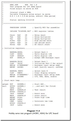
The same servo module can be connected directly to a PIC chip to provide a simple position control system. Figure 11.9 shows it connected to the LPC board for testing, as per the schematic in Figure 11.10, using program HOB1 (Program 11.4). The servo PWM input requires a TTL (transistoretransistor logic) positive pulse of between about 0.5 and 2.5 ms

PIC Microcontrollers-1299PIC Microcontrollers-1300

PIC Microcontrollers-1301

(depending on the servo specification), corresponding to the limits of travel, with the mid- position set by a pulse of about 1.5 ms. Some live calibration is normally required. The overall signal period is about 18 ms, but this is not critical.

In the test circuit, the PIC reads the pot input and sets the output pulse width accordingly, so the position of the servo follows the pot. To keep it simple, software loops are used to generate the PWM, but hardware timers and interrupts will typically be used in a more complete application.

1. Outline a method of controlling the speed of a small dc motor by PWM. Identify the main hardware components required. (4)

2. Explain how an incremental encoder can be used to provide speed and position feedback from a shaft to a microcontroller. (4)

3. Based on your answers to Questions 1 and 2, explain how the speed of a dc motor can be accurately controlled by a microcontroller using digital feedback. (4)

4. (a) Calculate the positional resolution (smallest step size) in degrees at the output shaft of a robot arm drive with a 90:1 gearbox, if a shaft encoder with 200 steps per revolution is attached to the motor shaft. (4)

(b) Calculate, to one significant figure, the positional resolution of a robot gripper positioned at 500 mm from the axis of rotation controlled by the above axis controller. (4)

Carry out the following investigations using test hardware or simulation, or both.

1. Construct the MOT2 board on stripboard and devise a test schedule. Confirm the correct operation of the hardware prior to fitting the PIC chip, OR download the simulation of the MOT2 board and confirm correct operation of DCM1.

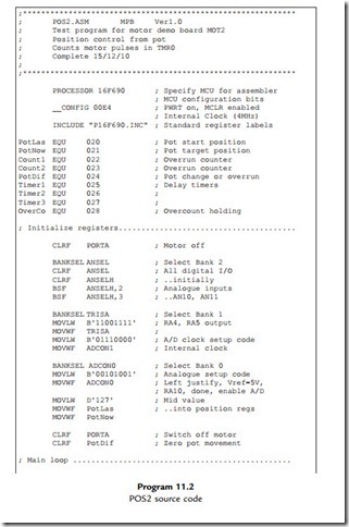
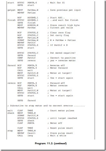
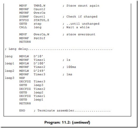
2. Evaluate the performance of the position control program POS2 in terms of speed of response, accuracy and reliability. What are the characteristics of the motor that affect the performance?

3. (a) Investigate the performance of the program CLS2 in terms of reliability, response time, range of control (maximum and minimum speeds). Devise a method of loading the motor to test the performance of the controller with varying loads (the speed should be held constant within limits).

(b) Modify CLS2 to read the input push buttons on the MOT2 board to increase or decrease the set speed.

4. (a) Modify the CLS2 program for the MOT2 board to use the timer interrupt to signal time out. Compare the performance of this alternative implementation with the original program.

(b) Modify the program CLS2 to use the port A interrupt to monitor the feedback from the motor. Compare the performance of this alternative implementation with the original program.

(c) Modify program CLS2 to control the set speed from the analogue input AN10.


PIC Motor Applications:Program Simulation

Program Simulation

The speed control application was tested in simulation mode (Figure 11.7). The forward drive, index sensor feedback and current monitoring signals can be seen on the

PIC Microcontrollers-1294

PIC Microcontrollers-1295PIC Microcontrollers-1296

virtual oscilloscope. The drive is operating at about 100 Hz and the feedback has a period of 100 ms, indicating a speed of 600 rpm (switch input ¼ 0xA0). The maximum motor speed (switch input ¼ FF) with this setup is just over 1000 rpm, the maximum displayed on the animated motor. The minimum speed (switch input ¼ 00) is just below 240 rpm.

The closed loop response can be tested at 600 rpm by opening the switch across the dummy load of 2 U. This adds extra resistance in series with the motor causing a drop in the ‘on’ current, hence the speed. The drive program must compensate by increasing the PWM drive to restore the set speed.

The current in the bridge drivers, forward and reverse, can be monitored across the 0.1 U sensing resistor. The ‘on’ current generates a voltage of about 0.4 V, indicating a current of 4 A. This can be connected to the analogue input AN11 by closing the jumper JP1 so it can be measured for control purposes. This could also be used to prevent excessive current in the bridge if, for example, the motor stalls.

Depending on the processing power of your computer, the simulation speed may drop back from real-time operation to a lower speed when testing this circuit. Check the status information below the edit screen: when the processor load reaches 100%, the simulation clock will slow down.


PIC Motor Applications:Hardware Testing

Hardware Testing

A hardware implementation can be tested using a dual-beam scope as indicated above. The correct function of the closed loop control process can be tested by setting the binary input to B‘10100000’ and checking the actual speed of the motor by measuring the period of the sensor pulse, which should be 100 ms. The binary input can then be varied, and the sensor period should vary in proportion, within limits stated above. The transient and start-up response can be examined by stalling the motor (if not too powerful), and studying the motor response as it locks on to the target speed. When the dummy load is switched in, the drive should compensate and maintain the speed of the motor by increasing the drive PWM MSR.

Evaluation and Improvements

The output was found to be slightly unstable around the target value, owing to the unequal timing of the alternative routes through the program, but this may not be significant in a real motor where the load inertia will tend to maintain a constant speed. Ideally, the PWM speed control should operate at a frequency above about 15 kHz. The demonstration program CLS2 operates at a lower frequency, because of the time required to sample the timer status and sensor input, and to complete the software loop for one drive cycle, which only uses an 8-bit count counter, Timer0. The performance will be improved by operating at the maximum MCU clock speed of 20 MHz, using interrupts and the hardware PWM output associated with 16-bit Timer2. Timer1 is a 16-bit counter, which would provide greater range and/or precision in the speed measurement. The Timer1 interrupt could be incorporated into signal timeout. Alternatively, the sensor pulse could be detected as a change at port A interrupt.


PIC Motor Applications:Counting Pulses

Counting Pulses

The accuracy of the speed measurement using this method will depend on the number of slots counted, because the error is always ± 1 slot. If the rev count were made over a period of 1 s at 10 pps, the precision would be 10% and the speed could only be corrected once per second. This response time is too slow for most practical purposes, so this option will be rejected. It would be viable if the encoder had more slots per revolution or the motor was running at high speed.

Measuring Pulse Period

At 10 pps, the target speed, the pulse period will be 100 ms. This can be measured using a 100 ms timer, which can be set up using the 8-bit TMR0 hardware counter/timer (see Chapter 6). The counter is driven by the instruction clock (1/4 of the MCU oscillator frequency). The timer prescaler allows this to be divided by 2, 4, 8, 16, 32, 64, 128 or 256, by setting a 3-bit code in the option register. If the MCU clock is set to 1 MHz, the timer clock rate is 250 kHz, with period 4 ms, with the maximum prescaler setting of 256, the longest period measurable will be 256 x 256 x 4 ¼ 26 2144 ms ¼ 262 ms. The count required, as a proportion of this maximum value, will be 100/262 x 256 ¼ 98 (to the nearest whole number). Recall that the timer counts up to FF then 00, when the overflow flag is set, so the timer must be preloaded with the complement of this value, 256 – 98 ¼ 158.

PWM Motor Control

The speed of the motor is controlled using PWM, which switches the motor current on and off over a fixed period cycle. The ratio of the on/off periods controls the average current, and hence the speed. A software delay loop will be used to generate a PWM drive signal to the motor, while running a hardware timer to generate a timing reference to compare with the sensor feedback each time round the motor delay loop. The mark/space ratio (MSR) is adjusted to control the speed. The target speed is set using the switch inputs to generate the timer preload value.

The process is illustrated in the timing diagram (Figure 11.5). The timing cycle starts at the rising edge of the sensor pulse when the timer is started. The program waits for the falling edge of the sensor pulse, then starts checking if the next pulse has arrived, or if the timer has timed out, once per motor cycle. If the speed is too low, the timer times out first, before the pulse arrives, so the speed must be increased for the next timing cycle. If the slot arrives before the timer has timed out, it means that the motor is running too fast, so the speed must be decremented for the next cycle. User flags have been defined, one to record the fact that the falling edge has been detected and acted upon (‘slot’ flag) and another to record the fact that the timer has been restarted (‘done’ flag), to make the program wait for the next slot to restart the timer. When the speed is correct, the speed correction will alternate between incrementing and decrementing.

Figure 11.6 shows the top-level flow chart for the program. This initializes the program and switches the motor on and off. ‘Speed’ is a user register that holds the value for the PWM ‘on’ time. The ‘off’ time is derived by complementing this value. The total count for each motor drive cycle is then 256, which means the frequency will remain constant. At the start of the main loop, on the rising edge of the sensor pulse, Timer0 is loaded with the 8-bit value read

PIC Microcontrollers-1292

PIC Microcontrollers-1293

from the switch bank. A low value will give a longer remaining count in Timer0, and a longer target cycle time, corresponding to a low speed. A high value will give a high target speed.

The main subroutine checks the input and timeout flag in a polling loop. If the timer times out before the next slot arrives, as is the case when starting up, the motor is going too slowly, so the PWM ‘on’ time is increased. When the motor is eventually going too quickly, the slot arrives before the timer has finished, so the ‘on’ time is reduced. The speed must be stopped from rolling over from FF (maximum) to 00 (minimum), so the speed value is tested for zero after incrementing or decrementing and set back to FF or 1, respectively.

When the motor is running at the correct speed, the sensor period should match the timer period. In practice, the motor will hunt around the target value owing to limited resolution in the measurements, program delays, motor imperfections and mechanical inertia. The source code is listed as CLS2.ASM in Program 11.3.


PIC Motor Applications:Closed Loop Speed Control

Closed Loop Speed Control

In this example, the motor board is to operate as a slave speed-controlled unit. A master controller supplies an 8-bit code to set the speed of the motor, with the local controller required to maintain it with a specified degree of precision. The MOT2 board allows for a test input at

PIC Microcontrollers-1289

PIC Microcontrollers-1290PIC Microcontrollers-1291

the switch bank to simulate this external demand. Alternatively, the required speed could be input as a data byte at a serial port.

Suppose that the motor is to be controlled to a speed of exactly 600 rpm. This will produce 10 pulses per second (pps) with a single slot in the wheel. This relatively low speed is used for simulation in ISIS, because the DCM rev counter only reads up to 999 rpm. Real hardware needs to be controlled at speeds up to at least 3000 rpm, using a higher MCU clock speed. The speed can be measured in one of two main ways: by counting sensor pulses over a measured time period, or by measuring the period between sensor pulses.