Hardware Prototyping:Hardware Construction

Hardware Construction

First, we will look briefly at some traditional techniques suitable for building one-off boards and prototypes, using the dice circuit in Figure 10.1. Then a slightly more elaborate general  purpose demonstration board will be designed and laid out in prototype form, and some programs provided to demonstrate its features and the related programming principles.

Printed Circuit Board

The PCB is the standard method for making electronic circuits. In its basic form, it starts life as a sheet of insulating glass fiber-reinforced epoxy resin, with a layer of copper on one side. The circuit connections are made by printing or photographically transferring a pattern of conducting tracks and pads onto the copper.

The layout for a simple PIC circuit is shown in Figure 10.2. It has a PIC 16F84A, push button, seven-segment display, buzzer and associated components. It can be programmed to operate as electronic dice, generating a random number between 1 and 6. The pattern of the copper tracks is shown, as well as the ‘silk screen’ printing, which is applied to the component side of the board to show where to place the components.

The layout is reversed, as it will be printed onto a translucent mask, which is then used to create the pattern of connections on the copper side of the board. The copper layer is coated with

PIC Microcontrollers-1254

a light-sensitive material, which is exposed to ultraviolet light through the mask. In the exposed areas of the board, the photosensitive material becomes soluble and is removed by a caustic solvent, exposing the copper below. This is then dissolved (etched) in an acid bath, leaving behind the copper layout where it was protected by the etch-resistant layer. The components are then fitted to the top side of the board, and the leads and pins soldered to the pads.

PIC Microcontrollers-1255

Once the layout has been designed, it can be used for batch production of the application hardware. Specialist companies are now often used to manufacture the boards direct from the file output of the PCB design software, as the cost of short production runs is now lower, owing to the application of advanced manufacturing techniques. The final product is shown in Figure 10.3.

Another simple single-sided layout is shown in Figure 10.4(a) on the edit screen of ARES PCB software. This package allows the ISIS schematic to be imported and converted to a layout for printing or export to a manufacturing system in a standard format (usually a Gerber file). Before transfer from ISIS, each component needs a suitable pin arrangement attached, depending on the actual component to be used. For example, the physical size of a resistor depends on its power rating, which consequently affects the pin spacing. Switches have a great variety of pin outs, or may be mounted off the board so suitable terminals must be provided. The ARES library provides standard pin-outs, or they can be created if necessary for non-standard components.

The netlist is then exported to ARES, and the list of components appears in a window at the left of the edit screen (Figure 10.4a). The components may be selected and placed individually on the layout edit screen and their positions adjusted for the most compact arrangement (auto- placement is also available). Initially, the connections are shown as direct lines between pins (‘rat’s nest’). These are converted into tracks when the auto-router utility is invoked. Final adjustments to the track layout are completed manually. If necessary, wire links may be used on a single-sided board to achieve a viable layout. A double-sided board simplifies the track arrangement a great deal, but plated through-holes or connecting pins are then necessary. When the layout is complete, a three-dimensional preview of the populated board can be generated (Figure 10.4b). The use of ARES is described in more detail in Appendix E.

PIC Microcontrollers-1256

The Microchip LPC demo board is an example of a double-sided board commercially produced in large quantities. Using both sides of a board allows it to be more compact overall, and simplifies the track layout. In general, tracks are oriented in a common direction on each side, perpendicular to the other side. More complex boards, such as the PC motherboard, have multiple layers sandwiched together to provide the large number of connections required by the system busses. Holes are plated through to make the connections between different layers, and a printed silk-screen layer carries the component labeling (or legend) on the top side. High-resolution printing techniques in the commercial production process allow a finer track width (where the current is small) and, overall, a more precise, compact layout.

Most production designs now use surface-mounted components, which are smaller and do not require through-holes for mounting, but are all soldered to the surface layer simultaneously by flow soldering. The surface-mount version of the PIC 16F887 can be seen on the Microchip 44-pin board. Full details of these boards can be downloaded from www. microchip.com, with the layouts provided in the user manuals. Both boards have prototyping areas so that simple peripheral circuits can be added without having to design a test board from scratch.

An alternative method for making simple prototype boards, which has recently become viable for the hobbyist, training organizations and small businesses, is the PCB mill. This is essentially a small 2.5D (dimensions) milling machine. An engraving tool is mounted on X, Y and Z (limited travel) axes and programmed to outline the copper tracks and pads to isolate them from the rest of the copper layer (Figure 10.5). This avoids the use of corrosive chemicals, and is viable for small-scale production.

PIC Microcontrollers-1257

Even with the current user-friendly ECAD packages, the PCB layout can take some time to create, and a considerable amount of skill is needed to use the software. Therefore, we will also look at how to prototype our hardware using traditional methods, which do not require specialist software or PCB fabrication equipment.

Breadboard

Breadboard (plugboard) has sets of miniature sockets laid out on a 0.1 inch grid which will accept the manual insertion of component leads and tinned copper wire (TCW) links (Figure 10.6a). It has rows of contacts interconnected in groups placed either side of the center line of the board, where the integrated circuits (ICs) are inserted, giving multiple contacts on each IC pin. At each side of the board, there are long rows of common contacts, which are used for the power supplies. Some types of breadboard are supplied in blocks that link together to accommodate larger circuits, or are mounted on a base with built-in power supplies.

The layout for a simple circuit is shown in Figure 10.6(b), with a PIC 16F84A driving a light- emitting diode (LED) at RB0 via a current-limiting resistor. The only other components required are a capacitor and resistor to form the clock circuit, but we must not forget to connect the !MCLR (Master Clear) pin to the positive supply, or the chip will not run. The chip could now be programmed to flash the output at a specified rate.

Breadboard circuits can be built quickly, with no special tools required, other than a supply of insulated wire (recycled telephone cables are ideal) and wire cutters. However, the connections

PIC Microcontrollers-1258

are relatively unreliable, so bad connections are likely in more complicated circuits. Therefore, a method of producing prototype circuits with more reliable soldered connections might be preferred.

Stripboard

Stripboard (veroboard) requires no special tools or chemical processing. The components are connected via copper tracks laid down in strips on a 0.1 inch grid of pinholes in an insulating board (Figure 10.7a).

The components are soldered in place and the circuit is completed using wire links on the component side soldered to the tracks on the copper side. The tracks must be cut where necessary to isolate the connection nodes in the circuit using a hand drill. The components are generally placed across the tracks, so that each pin connects with a separate track. The tracks must be cut between the rows of pins in each dual in-line (DIL) chip. Care is required to avoid dry joints (too little solder) or short-circuits between tracks due to solder splashes and whiskers (too much solder). A manual drawing may used to draft the layout, if necessary, but experienced constructors will often build the circuit ad hoc, with maybe some additional wastage of board area.

Figure 10.7(b) shows how the simple PIC circuit can be laid out for construction on stripboard using general purpose drawing tools, such as those provided with Word®. In the word processor, the drawing toolbar needs to be switched on, and page layout view selected. In the Draw menu,

the grid should be switched on and set to 0.1 inch; this allows layouts to be drawn actual size, since this is the spacing between standard in-line pins. The circuit can then be drawn using suitable line styles, text boxes and so on. When finished, use the Select Objects tool to select the whole drawing and Group it in the Draw menu. This prevents text cursor movement from disrupting the drawing, and the whole diagram can be repositioned on the page if required.

Naturally, the circuit can also be hand-drawn in the traditional manner.


Hardware Prototyping:Program DICE1

Program DICE1

This program will generate a random number at the display between 1 and 6 when the input button in pressed. A continuous loop will increment a register from 1 to 6, and back to 1. The loop is stopped when the button is pressed and the number displayed. The display is retained when the button is released.

First, the allocation of the segments to the pins on the display chip must be established. The segments of the display are labeled from a to g, as shown in Figure 10.15. They must be lit in the appropriate combinations to give each display number; for instance, segments ‘b’ and ‘c’ must be lit for the number ‘1’ to be displayed. A table is useful here to work out the codes required for output to the display (Table 10.2).

The display is active high in operation. This means a 1 at the pin will light that segment. This arrangement is also described as common cathode, as all the LED cathodes are connected together at the common terminal. A common anode display will therefore operate active low. The binary or hexadecimal code for each digit will be included in the program in the form of a program data table.

The program represented in the flowchart (Figure 10.16) uses a spare register as a counter, which is continuously decremented from 6 to 0. When the button is pressed, the current number is used to select from the table of codes using the method described in Program 10.2. This results in the pseudo-random number code being displayed, and remaining visible until the button is pressed again. Because the number is selected by manually stopping a fast loop, the number cannot be predicted. In the flowchart, the jump destinations have been labeled, and these labels will be used in the program source code. The table subroutine is also named ‘table’ to match the source code subroutine start label.


Hardware Prototyping:Hardware Design

Hardware Design

Before computer-based electronic computer-aided design (ECAD) was widely available, circuits would be designed as sketches on paper and a layout produced manually. In the absence of fast and powerful computer simulation methods such as SPICE, this process relied more heavily on the experience of the design engineer to be able to predict the circuit performance from theoretical knowledge and practical experience. Numerous prototypes might be needed to arrive at a working solution.

Since the development of increasingly powerful desktop computers, the design process has been radically improved. The designer still has to come up with the original ideas, but circuits can now be rapidly drawn and tested on screen, and a working design quickly produced. The hardware prototype is much more likely to work first time, or at least require less development time. The time taken from design concept to market is regarded as a major competitive factor, so ECAD is now a vital tool for the electronics engineer, just as computer-aided design (CAD) has become in mechanical engineering.

A circuit schematic can now be created, tested and converted into a PCB layout within a single software package, such as Proteus VSM. Complete libraries of all the most commonly used components and microcontrollers are available, which consist of a mathematical model, on- screen circuit symbol and, in selected cases, a physical component pin-out for each. A set of animated components also allows interactive simulation. A circuit can be drawn on screen, the application program attached to the microcontroller and the program tested by operating the on-screen inputs, such as switches and or a keypad, with the mouse. The outputs are then seen

PIC Microcontrollers-1253

on simulated displays (LED and LCD), or operate animated output devices, such as relays and motors. Examples can be seen in previous chapters.

A further example is shown in Figure 10.1, which will be converted into a PCB layout. It is an electronic dice board with a push button, seven-segment display and buzzer controlled by a PIC 16F84A. It can be programmed to display a random number between 1 and 6 when the button is pressed.

When a suitable program is assigned to the PIC in the simulation (see below), the circuit becomes interactive on screen. When the switch is operated, the display will operate in the same way as the real device. If the chip is programmed to generate a sound output via the buzzer, the waveform can be displayed on a virtual oscilloscope, and reproduced at the PC audio output. The techniques for developing the firmware (Flash ROM software) have been explained in detail in previous chapters.


Application Design:Software Design

Software Design

We can now start work on the software using a flowchart to outline the program. A few simple rules will be used to help devise a working assembly code program; these have been discussed in more detail in Chapter 2.

A program consists of a sequence of instructions that are executed in the order that they appear in the source code, unless there is an instruction or statement that causes a jump, or branch. Usually jumps are ‘conditional’, which means that some input or variable condition is tested and the jump is made, or not, depending on the result. In PIC assembler, ‘Bit Test and Skip if Set/Clear’ and ‘Decrement/Increment File Register and Skip if Zero’ provide conditional branching when used with a ‘GOTO label’ or a ‘CALL label’ immediately following.

A loop can be created by jumping back at least once to a previous instruction. In our standard delay loop, for instance, the program keeps jumping back until a register that is decremented within the loop reaches zero. In high-level languages, conditional operations are created using

IF (a condition is true) THEN (do a sequence), and loops created using statements such as DO (a sequence) WHILE (a condition is true/not true). This terminology can be used in a program outline to clarify the logical sequences required.

MOT1 Outline Flowchart

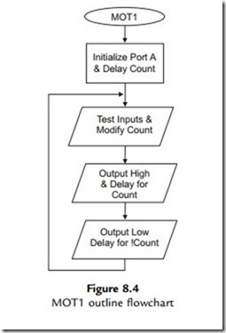
Flowcharts illustrate the program sequence, selections and iterations in a pictorial way, using a simple set of symbols. Some basic rules for constructing flowcharts are all that are needed to ensure consistency in their use, leading to well-structured programs. An outline flowchart for the motor speed control program MOT1 is shown in Figure 8.4.

The outline flowchart shows a sequence where the inputs (Run, Speed Up and Speed Down) are checked and the delay count is modified if either of the speed control inputs is active. The output is then set high and low for that cycle, using the calculated delays to give the MSR. The loop repeats endlessly, unless the reset is operated. The reset operation is not represented in the flowchart, because it is an interrupt, and therefore may occur at any time within the loop. The program name, MOT1, is placed in the start terminal symbol. Most programs need some form of initialization process, such as setting up the ports at the beginning of the main program loop. This will normally only need to be executed once. Any assembler directives, such as label equates, should not be represented, as they are not part of the executable

PIC Microcontrollers-1234

In common with most ‘real-time’ applications, the program loops continuously until reset or switched off. Therefore, there is an unconditional jump at the end of the program back to start, but missing out the initialization sequence. Since no decision is made here, the jump back is simply represented by the arrow, and no process symbol is needed. It is suggested here that the loop back should be drawn on the left side of the chart, and any loop forward on the right, unless it spoils the symmetry of the chart or causes line segment cross-overs. Note that when branching, the flow junctions must be BETWEEN process boxes, to preserve a single input, single output rule for each process. Each process then always starts and ends at the same point.

MOT1 Detail Flowchart

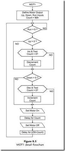
The outline flowchart given in Figure 8.4 may show enough information for an experienced programmer. If more detail is needed, boxes in the main program can be elaborated until there is enough detail for the less experienced programmer to translate the sequence into assembly code. A detail flowchart is shown in Figure 8.5.

After the initialization sequence, a set of conditional jumps is required to enable the motor, check the ‘up’ and ‘down’ inputs, and test for the maximum and minimum values of the value of ‘Count’ (FF and 01). Two different forms of the decision box have been used in this example, both of which may be seen. The diamond-shaped decision symbol is used here to represent a ‘Bit Test and Skip If Zero/Not Zero’ operation, while the elongated symbol represents an ‘Increment/Decrement and Test for Zero’ operation, which essentially combines two instructions in one. In either case, the decision box should contain a question, with its outputs representing a ‘Yes’ or ‘No’ result of the test. Note that only the result producing the jump needs to be specified.

‘Decrement and Skip if Zero’ is used to create the software delay loop. Two different delays are required, one for the mark time, one for the space. Since the delay needed is relatively short, and only a single loop is needed, a delay subroutine is not necessary.

Flowchart Symbols

A minimal set of flowchart symbols is shown in Figure 8.6. The data flowchart symbols provided in Word (Autoshapes) may be used, but they do not necessarily have the same meaning here. The text can be inserted via the drawing object properties menu (right click, add text).

Terminals

These symbols are used to start or end the main program or a subroutine. The program name or routine start label used in the source code should be specified in the start box. If the program loops endlessly the END symbol is not needed, but RETURN must always be used to terminate a subroutine. In PIC programming, use the project name (e.g. MOT1) in the start symbol of the

PIC Microcontrollers-1235

PIC Microcontrollers-1236

main program, and the subroutine start address label in subroutine start symbols. Terminals have only one input or output.

Processes

The process box is a general purpose symbol that represents a sequence of instructions, possibly including loops inside it. The top-level flowchart of a complex program can be simplified, with a lot of detail concealed in each box. A subroutine is a process that will be implemented in the source code as a separate block, and may be used more than once within a program. It may be expanded into a separate subroutine flowchart, using the same name in the start symbol as that shown in the calling process. Subroutines can be created at several levels in a complex program. Processes should have only one input and one output.

Input/Output

This represents processes whose main function is input or output using a port data register in the microcontroller. Use a statement in the box that describes the general effect of the I/O operation, for example, ‘Switch Motor On’ rather than ‘Set RA0’. This will make the flowchart easier to understand. This symbol should also have only one input and one output.

Decisions

The decision symbol contains a description of the conditional branch as a question. There will be two alternative exit paths, for the answers ‘yes’ and ‘no’. Only the arrow looping back

or forward needs to be labeled ‘yes’ or ‘no’; the default option, which continues the program flow down the center of the chart, need not be labeled. In PIC assembly language, this symbol would refer to the ‘Test and Skip’ instructions. In the MOT1 detailed flowchart, an enlarged decision box is used to represent the ‘Decrement/Increment and Skip if Zero’ operation. This symbol allows more text inside, so is a useful alternative to the standard diamond shape. The decision symbol thus contains a logical question, and has one input and two outputs, ‘yes’ or ‘no’.

Flowchart Structure

In order to preserve good program structure, there should be single entry and exit points to and from all process blocks, as illustrated in the complete flowcharts. Loops should rejoin the main flow between symbols, and not connect into the side of a process symbol, as is sometimes seen. Terminal symbols have a single entry or exit point. Decisions in assembler programs only have two outcomes, branch or not, giving two exits. Loops back should be drawn on the left of the main flow, and loops forward on the right of the main flow, if possible. For the main flow down the page, the arrowheads may be omitted as forward flow is clearly implied.

Connections between pages are sometimes used in flowcharts, shown by a circular labeled symbol. It is recommended here that such connections be avoided; it should be possible to represent a well-structured program with a set of separate flowcharts, each of which should fit on one page. An outline flowchart should be devised for the main sequence, and then each process detailed with a separate flowchart, so that each process can be implemented as a subroutine or macro. In this case, the main program sequence should be as small as possible, consisting of subroutine calls and the main branching operations.

Therefore, the program should initially be represented as an outline flowchart on a single page, and each process expanded using subroutines or functions on separate pages. Keep expanding the detail until each block can be readily converted to source code statements. A well- structured program like this will be easier to debug and modify. Subroutines can be ‘nested’, to a depth that depends on the MCU hardware stack size (including interrupts). Mid-range PICs have space for eight return addresses in a hardware stack, which means that only eight levels of subroutine or interrupt are allowed.

Structure Chart

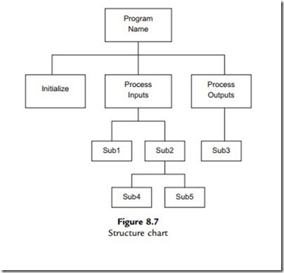
The structure chart is another method for representing complex programs. Each program

block is placed in a hierarchical diagram to show how it relates to the rest of the program. This technique is most commonly used in data processing and business applications running on larger computer systems, but may be useful for more ambitious microcontroller applications.

The program shown in the structure diagram (Figure 8.7) has four levels. The main program calls subroutines to initialize, process inputs and process outputs. The input processing routine in turn calls Sub1 and Sub2 subroutines. Output processing only requires Sub3, but Sub2 calls Sub4 and Sub5 at the lowest level. At this level, 3 stack locations will be used up.

Pseudocode

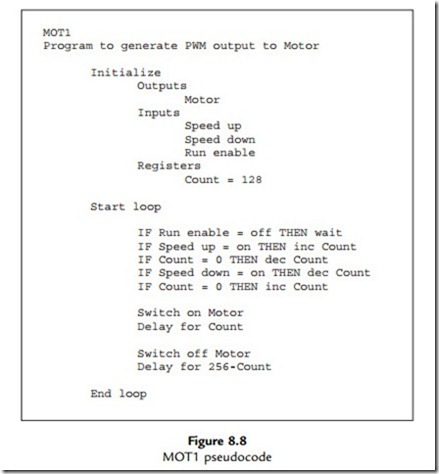
Pseudocode is a text outline of the program design. The main operations are written as descriptive statements that are arranged as functional blocks. The structure and sequence are represented by suitable indentation of the blocks, as is the convention for high-level languages. An outline of MOT1 is shown in Figure 8.8.

The pseudocode version of the program uses high-level style syntax, such as IF … THEN, to describe the selections in the program. It has the advantage that no drawing is required, and the

PIC Microcontrollers-1237

PIC Microcontrollers-1238

pseudocode can be entered directly into the text editor used for writing the source code. It can be started as a brief outline and developed in stages, until it is ready to be translated into assembler syntax. The pseudocode can be left in the source code as the basis of program comments, or replaced, whichever suits the programmer. Although used here to represent an assembler program, pseudocode is probably most useful for developing ‘C’ programs for applications for the more powerful PIC microcontrollers.


Program Debugging:Interactive Debugging

Interactive Debugging

Interactive simulation of microcontroller circuits provides a powerful extra dimension in application design and debugging. Proteus VSM offers a complete design package, with schematic editing and capture, using a library of components which provides a graphical symbol for the schematic, a mathematical model for circuit analysis and component pin-out for use in the circuit layout. These are provided in two software packages, ISIS schematic capture and ARES PCB layout. Detailed guidance on using Proteus VSM is given in Appendix E.

ISIS Schematic

The application design concept may be outlined using a block diagram and converted to provisional circuit, which can be entered into ISIS. The components are selected from the library of parts, placed on the screen and connected using virtual wiring. The result is a schematic such as that for MOT1 seen in Figure 9.3, which includes a virtual oscilloscope for monitoring the output.

Mixed mode simulation uses standard circuit modeling techniques for the analogue parts of the circuit. For example, the mathematical model for a resistor is V ¼ IR. The behavior of reactive components (e.g. capacitors and motors) is modeled using complex mathematics, which is used to represent the phase relationships between voltage and current, and hence transient and frequency response in switching circuits. Overall, the analogue parts of a circuit are represented as a set of nodes connected together by these components, forming a mesh. This is then represented by a set of simultaneous equations in the form of a matrix, which can be solved for any given input signals. This process is repeated at intervals to predict the output and provide a dynamic, interactive model of the circuit.

Modeling the digital circuit elements, on the other hand, is simply a question of representing the logical processes performed by the components using a suitable logical model. For example, the output of an AND gate is A$B (see Appendix B). The microcontroller is represented by a combination of its internal logic and the application program attached. The effects of all types of component can then be combined to give a reasonably complete model

PIC Microcontrollers-1248

of the whole circuit. The main limitation of the simulation is that it sometimes fails to converge on a solution, especially in complex or high-speed circuits. The model then needs to be simplified, resulting in a less accurate simulation. Of course, the model is only an approximation to the real circuit in any case, especially when modeling complex devices such as motors.

The components used in MOT1 are mostly generic types, that is, they do not represent a specific component. For example, the resistor has a model described as an ‘analogue primitive’ or generic model. The capacitor is the same. The push button is an active device, that is, it can be operated on screen, in either transient (click on button) or latched (click on control spot) mode. The generic NMOS FET (see Appendix B) could be replaced by a specific component that has a model tailored to the operating parameters of that particular device. The dc motor parameters can be changed in the properties dialogue (i.e. operating voltage, nominal speed and coil resistance).

The microcontroller, in contrast, is a specific device from a particular manufacturer. It needs a machine code program (hex file) to be attached to determine its operation. This can be created in a built-in editor and, if a PIC, assembled using a copy of MPASM included with the simulation package. The hex file is attached via the component properties dialogue (double- left-click on the component). The clock speed (100 kHz) and configuration word can also be defined in this dialogue. The components are selected from the component libraries as illustrated in Figure 9.4.

The oscilloscope is one of a selection of virtual instruments. The power supplies are represented by a ground (0 V) connection and a power terminal whose supply voltage is

PIC Microcontrollers-1249

specified by the label (þ5 V and þ12 V). These additional items are selected via the mode toolbar buttons at the left of the edit window (see Appendix E for details).


Application Design:Software Design

Software Design

We can now start work on the software using a flowchart to outline the program. A few simple rules will be used to help devise a working assembly code program; these have been discussed in more detail in Chapter 2.

A program consists of a sequence of instructions that are executed in the order that they appear in the source code, unless there is an instruction or statement that causes a jump, or branch. Usually jumps are ‘conditional’, which means that some input or variable condition is tested and the jump is made, or not, depending on the result. In PIC assembler, ‘Bit Test and Skip if Set/Clear’ and ‘Decrement/Increment File Register and Skip if Zero’ provide conditional branching when used with a ‘GOTO label’ or a ‘CALL label’ immediately following.

A loop can be created by jumping back at least once to a previous instruction. In our standard delay loop, for instance, the program keeps jumping back until a register that is decremented within the loop reaches zero. In high-level languages, conditional operations are created using

IF (a condition is true) THEN (do a sequence), and loops created using statements such as DO (a sequence) WHILE (a condition is true/not true). This terminology can be used in a program outline to clarify the logical sequences required.

MOT1 Outline Flowchart

Flowcharts illustrate the program sequence, selections and iterations in a pictorial way, using a simple set of symbols. Some basic rules for constructing flowcharts are all that are needed to ensure consistency in their use, leading to well-structured programs. An outline flowchart for the motor speed control program MOT1 is shown in Figure 8.4.

The outline flowchart shows a sequence where the inputs (Run, Speed Up and Speed Down) are checked and the delay count is modified if either of the speed control inputs is active. The output is then set high and low for that cycle, using the calculated delays to give the MSR. The loop repeats endlessly, unless the reset is operated. The reset operation is not represented in the flowchart, because it is an interrupt, and therefore may occur at any time within the loop. The program name, MOT1, is placed in the start terminal symbol. Most programs need some form of initialization process, such as setting up the ports at the beginning of the main program loop. This will normally only need to be executed once. Any assembler directives, such as label equates, should not be represented, as they are not part of the executable

PIC Microcontrollers-1234

In common with most ‘real-time’ applications, the program loops continuously until reset or switched off. Therefore, there is an unconditional jump at the end of the program back to start, but missing out the initialization sequence. Since no decision is made here, the jump back is simply represented by the arrow, and no process symbol is needed. It is suggested here that the loop back should be drawn on the left side of the chart, and any loop forward on the right, unless it spoils the symmetry of the chart or causes line segment cross-overs. Note that when branching, the flow junctions must be BETWEEN process boxes, to preserve a single input, single output rule for each process. Each process then always starts and ends at the same point.

MOT1 Detail Flowchart

The outline flowchart given in Figure 8.4 may show enough information for an experienced programmer. If more detail is needed, boxes in the main program can be elaborated until there is enough detail for the less experienced programmer to translate the sequence into assembly code. A detail flowchart is shown in Figure 8.5.

After the initialization sequence, a set of conditional jumps is required to enable the motor, check the ‘up’ and ‘down’ inputs, and test for the maximum and minimum values of the value of ‘Count’ (FF and 01). Two different forms of the decision box have been used in this example, both of which may be seen. The diamond-shaped decision symbol is used here to represent a ‘Bit Test and Skip If Zero/Not Zero’ operation, while the elongated symbol represents an ‘Increment/Decrement and Test for Zero’ operation, which essentially combines two instructions in one. In either case, the decision box should contain a question, with its outputs representing a ‘Yes’ or ‘No’ result of the test. Note that only the result producing the jump needs to be specified.

‘Decrement and Skip if Zero’ is used to create the software delay loop. Two different delays are required, one for the mark time, one for the space. Since the delay needed is relatively short, and only a single loop is needed, a delay subroutine is not necessary.

Flowchart Symbols

A minimal set of flowchart symbols is shown in Figure 8.6. The data flowchart symbols provided in Word (Autoshapes) may be used, but they do not necessarily have the same meaning here. The text can be inserted via the drawing object properties menu (right click, add text).

Terminals

These symbols are used to start or end the main program or a subroutine. The program name or routine start label used in the source code should be specified in the start box. If the program loops endlessly the END symbol is not needed, but RETURN must always be used to terminate a subroutine. In PIC programming, use the project name (e.g. MOT1) in the start symbol of the

PIC Microcontrollers-1235

PIC Microcontrollers-1236

main program, and the subroutine start address label in subroutine start symbols. Terminals have only one input or output.

Processes

The process box is a general purpose symbol that represents a sequence of instructions, possibly including loops inside it. The top-level flowchart of a complex program can be simplified, with a lot of detail concealed in each box. A subroutine is a process that will be implemented in the source code as a separate block, and may be used more than once within a program. It may be expanded into a separate subroutine flowchart, using the same name in the start symbol as that shown in the calling process. Subroutines can be created at several levels in a complex program. Processes should have only one input and one output.

Input/Output

This represents processes whose main function is input or output using a port data register in the microcontroller. Use a statement in the box that describes the general effect of the I/O operation, for example, ‘Switch Motor On’ rather than ‘Set RA0’. This will make the flowchart easier to understand. This symbol should also have only one input and one output.

Decisions

The decision symbol contains a description of the conditional branch as a question. There will be two alternative exit paths, for the answers ‘yes’ and ‘no’. Only the arrow looping back

or forward needs to be labeled ‘yes’ or ‘no’; the default option, which continues the program flow down the center of the chart, need not be labeled. In PIC assembly language, this symbol would refer to the ‘Test and Skip’ instructions. In the MOT1 detailed flowchart, an enlarged decision box is used to represent the ‘Decrement/Increment and Skip if Zero’ operation. This symbol allows more text inside, so is a useful alternative to the standard diamond shape. The decision symbol thus contains a logical question, and has one input and two outputs, ‘yes’ or ‘no’.

Flowchart Structure

In order to preserve good program structure, there should be single entry and exit points to and from all process blocks, as illustrated in the complete flowcharts. Loops should rejoin the main flow between symbols, and not connect into the side of a process symbol, as is sometimes seen. Terminal symbols have a single entry or exit point. Decisions in assembler programs only have two outcomes, branch or not, giving two exits. Loops back should be drawn on the left of the main flow, and loops forward on the right of the main flow, if possible. For the main flow down the page, the arrowheads may be omitted as forward flow is clearly implied.

Connections between pages are sometimes used in flowcharts, shown by a circular labeled symbol. It is recommended here that such connections be avoided; it should be possible to represent a well-structured program with a set of separate flowcharts, each of which should fit on one page. An outline flowchart should be devised for the main sequence, and then each process detailed with a separate flowchart, so that each process can be implemented as a subroutine or macro. In this case, the main program sequence should be as small as possible, consisting of subroutine calls and the main branching operations.

Therefore, the program should initially be represented as an outline flowchart on a single page, and each process expanded using subroutines or functions on separate pages. Keep expanding the detail until each block can be readily converted to source code statements. A well- structured program like this will be easier to debug and modify. Subroutines can be ‘nested’, to a depth that depends on the MCU hardware stack size (including interrupts). Mid-range PICs have space for eight return addresses in a hardware stack, which means that only eight levels of subroutine or interrupt are allowed.

Structure Chart

The structure chart is another method for representing complex programs. Each program

block is placed in a hierarchical diagram to show how it relates to the rest of the program. This technique is most commonly used in data processing and business applications running on larger computer systems, but may be useful for more ambitious microcontroller applications.

The program shown in the structure diagram (Figure 8.7) has four levels. The main program calls subroutines to initialize, process inputs and process outputs. The input processing routine in turn calls Sub1 and Sub2 subroutines. Output processing only requires Sub3, but Sub2 calls Sub4 and Sub5 at the lowest level. At this level, 3 stack locations will be used up.

Pseudocode

Pseudocode is a text outline of the program design. The main operations are written as descriptive statements that are arranged as functional blocks. The structure and sequence are represented by suitable indentation of the blocks, as is the convention for high-level languages. An outline of MOT1 is shown in Figure 8.8.

The pseudocode version of the program uses high-level style syntax, such as IF … THEN, to describe the selections in the program. It has the advantage that no drawing is required, and the

PIC Microcontrollers-1237

PIC Microcontrollers-1238

pseudocode can be entered directly into the text editor used for writing the source code. It can be started as a brief outline and developed in stages, until it is ready to be translated into assembler syntax. The pseudocode can be left in the source code as the basis of program comments, or replaced, whichever suits the programmer. Although used here to represent an assembler program, pseudocode is probably most useful for developing ‘C’ programs for applications for the more powerful PIC microcontrollers.


Program Debugging:VSM Debugging

VSM Debugging

When the circuit is complete, and the MCU program attached, the simulation can be run. The logic levels on each connection are displayed as blue (low) and red (high). Clicking on the Run button in the schematic should make the motor appear to turn. The Up button should make it speed up and the Down button slow down. The Reset will restart it at the default speed. This can be seen more easily by displaying the PWM signal on the virtual oscilloscope. If the program needs debugging, the source code can be displayed and single stepping and breakpoints applied. A screenshot of the VSM debugging setup is shown in Figure 9.5.

The benefits of both the more extensive debugging and project management tools in MPLAB and the user-friendly interface of Proteus VSM can be realized by running VSM as the debugging tool from within MPLAB (Figure 9.6). When selected as the debugging tool in the MPLAB menu, a VSM viewing window opens, allowing the current program in memory to be run in interactive mode. Debugging and program modification are still carried out using the

PIC Microcontrollers-1250

same MPLAB controls and facilities. However, if the schematic needs modifying, it must be re-edited in ISIS itself.


Program Debugging:Hardware Testing

Hardware Testing

Hardware construction will be covered in more detail in Chapter 10. For the moment, we will assume that suitable hardware has been constructed for MOT1 and we are ready to test it. When the program has been fully debugged in a simulator, it can be downloaded to the chip. In some cases, the chip must be programmed before fitting, specifically 16F84A-based circuits. For most current PIC chips, however, it is preferable to program it in-circuit via the six-pin in-circuit serial programming (ICSP) connection (see Chapter 7). In-circuit debugging, as described in Chapter 7, can also be used in the final stages of testing. This allows the program to be exercised in conjunction with the final hardware, using the debugging tools in MPLAB. The state of the registers in response to real inputs can then be monitored for fault- finding purposes.

The target hardware layout and connections should be carefully checked and tested before inserting the chip. The populated circuit board should be inspected for correct assembly; wrong component orientation, solder bridges between tracks and dry joints are common faults. The connections can be buzzed out with a continuity tester and checked against the circuit diagram.

Before fitting the microcontroller chip, it is a good idea to apply power and check the rest of the circuit. Make sure the components connected to the chip outputs can be safely powered up with an open circuit input. For example, in the MOT1 circuit, the field effect transistor (FET) gate input should not be allowed to float, so there is a pull-down resistor fitted. The supply current should not be excessive, and components should be checked for overheating. The voltages at the chip power supply pins (VDD and VSS) of the chip should also be checked, as incorrect connection of the supply is likely to damage most integrated circuits.

If all is well, switch off the power and fit the chip using a suitable tool. Antistatic precautions should be observed, but PIC chips have not been found to be particularly sensitive in practice.

Make sure it is the right way round! Pin 1 should be marked on the board. Switch on and check that the chip is not overheating or drawing excessive current. If left to overheat for more than a few seconds, the chip will probably be destroyed.

Connect an oscilloscope to the output. On power-up, there should be no output from MOT1. When the ‘Run’ button is pressed, the default output waveform with a 50% MSR should be observed, running at a frequency of about 30 Hz. The speed ‘Up’ and ‘Down’ buttons should be operated to ensure that the speed control stops at the minimum and maximum value, and does not roll over from zero to full speed in one step. Note that the program algorithm does not give an MSR of 100% or 0%, but stops one step short of the maximum and minimum. Since there are 255 steps altogether, the step size is less than 1%.

The circuit should also be tested for fail-safe operation, that is, no unplanned or potentially dangerous output is caused by an incorrect input operating sequence. In this case, operating both the ‘Up’ and ‘Down’ buttons together would be an erroneous input combination, which should result in no change in speed, because the increment and decrement operations cancel out.

Other examples of potential problems that would need to be considered are input switch bounce, variation in component performance (check specifications), dynamic operation of motor, minimum MSR required to make the motor run, and so on. Complex applications are likely to have more potentially incorrect input conditions and component-related problems, but the test schedule should ideally anticipate all possible fault modes (not easy!). If the circuit is being produced on a commercial basis, a formal test schedule would be needed, and the performance certificated as being correct to the product specification.

A basic test schedule for the MOT1 program running in a PIC 16F84A has already been outlined for the simulator test in Table 9.2, and this can be adapted for hardware testing. Additional documentation should be prepared according to circumstances (education, commercial, research) to provide the application user or product customer with the relevant information on using the system.

1. Explain briefly the difference between syntax and logical program errors, and how they are detected. (4)

2. How are the following used in program debugging: single stepping, breakpoint, pin stimulus, watch window? (4)

3. An instruction in the program memory listing appears as follows:

0005 1A05 start btfsc 0x5,0x4

Explain the meaning of each of the six elements in the line, such that its correct effect can be predicted when debugging. (6)

4. State two advantages of interactive debugging using Proteus VSM. (2)

5. State two checks to be carried out before powering up a new prototype microcontroller board. (4)

1. (a) In MPLAB, open a source file edit window, enter or download the source code for MOT1 and assemble it using the Quickbuild option. Note any error messages generated. If the program assembles correctly first time, put some deliberate errors in the source code and inspect the error messages.

(b) In MPLAB, create a project MOT1, assign MOT1.ASM to the project, reassemble and test the program using scheduled inputs as described in Section 9.2.5.

2. (a) Design an application for the LPC demo board with 16F690 to control the brightness of

an LED using PWM. When the input button is pressed, the LED should increase in brightness up to a maximum and then reduce back to the minimum, so that it can be stopped at any point by releasing the button. Demonstrate correct operation in MPLAB using an asynchronous stimulus.

(b) If Proteus VSM for 16 series PIC is available, download the simulation of the LPC board to test the dimmer program interactively. Modify it so that the LED brightness is controlled by the pot.


Application Design:Program Implementation

Program Implementation

When the program logic has been worked out using flowcharts, or otherwise, the source code can be entered using a text editor. Normally, the program editor is part of an integrated development package such as MPLAB. Most programming languages are now supplied as part of an integrated edit and debug package. Assembler source code can also be entered directly into the Proteus VSM system, which includes an editor and the PIC assembler, and this is preferable where the schematic has already been created in ISIS and the program is not too complex.

Flowchart Conversion

The program design method should be applied so as make the program as easy as possible to translate into source code. The PIC has a ‘reduced’ instruction set, meaning that the number of available instructions has deliberately been kept to a minimum to increase the speed of execution and reduce the complexity of the chip. While this also means that there are fewer instructions to learn, the assembler syntax (the way the instructions are put together) can be a little trickier to work out. For example, the program branch is achieved using the ‘Bit Test and Skip’ instruction. In CISC assembly code languages, branching and subroutine calls are implemented using single instructions. The PIC assembler requires two instructions. However, recall that ‘Special Instructions’ (essentially predefined macros) are available which combine ‘test’, ‘skip’ and ‘goto’ instructions to provide equivalents to conventional conditional branching instructions (see Chapter 6).

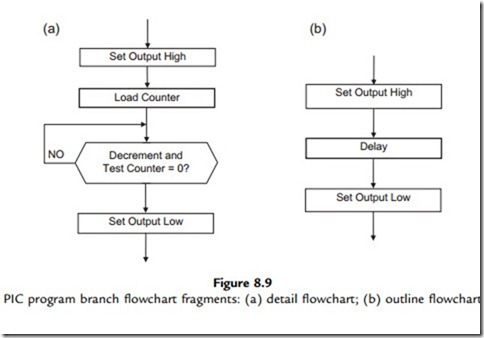
The representation of the program with different levels of detail is illustrated in Figure 8.9. Figure 8.9(a) shows the process in enough detail that each process box converts into only one or two lines of code. This may be necessary when learning the programming syntax. Later, when the programmer is more familiar with the language and the standard processes that tend to recur, such as simple loops, then a more condensed flowchart may be used, such as Figure 8.9(b), where the loop is concealed within the ‘delay’ process. As we have seen above,

PIC Microcontrollers-1239

PIC Microcontrollers-1240

this process can also be written as a separate, reusable, software component: a subroutine. The corresponding source code fragment is shown in Table 8.3.

Another limitation in PIC 16 assembler is found when moving data between registers. It is not possible to copy data directly between file registers; it has to be moved into the working register (W) first, and then into the file register. This requires two instructions instead of the single instruction available in other processors. This problem is overcome to some extent by the availability of the destination register option with the byte processing operations, which allows the result to be placed in W or F, as required. Nevertheless, the advantage of simplicity in PIC assembly language outweighs these limitations, especially in the early stages of learning.

MOT1 Source Code

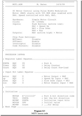
The program source code for the MOT1 program is listed in Program 8.1. The program produces the PWM output by toggling RA0 with a delay. A register labeled ‘timer’ holds the current value for the ‘on’ delay. The program does not use a subroutine for the delay, because the ‘timer’ value has to be modified for the ‘off’ delay. Note the use of the COMF instruction, which complements the contents of the timer register, which effectively subtracts the value from 256. The total PWM cycle time stays constant as a result. When incremented, the ‘timer’ value has to be checked to prevent it rolling over from FF to 00, by decrementing it again if the new value is zero. The roll-under at the low end of the scale is prevented in a similar way.

The program source code has instruction mnemonics in upper case to match the instruction set in the data sheet. However, by default, they are not case sensitive, so you will often see them in lower case. On the other hand, labels ARE case sensitive, so they must match exactly when

PIC Microcontrollers-1241

PIC Microcontrollers-1242

declared and used. The label case sensitivity can be switched off as an assembler option if you wish. Upper case characters for the special function register names (PORTA) have been used to match the register names used in the data sheet, and lower case characters with the first letter capitalized used for general purpose registers (Timer, Count). The bit labels are lower case (motor, up, down, run), as are the address labels. Using source code editing conventions like this is not obligatory, but consistent layout and presentation improves program readability and makes it easier to understand.

Most programming languages allow comments to be included in the source code as a debugging aid for the programmer, and information for other software engineers who may need to fix the code at a later date. Comments in PIC source code are preceded by a semicolon; the assembler ignores any source code text following, until a line return is detected.

A header should always be created for the main program and the associated routines. It should contain relevant information for program downloading, debugging and maintenance.

Examples have already been given. The layout should be standardized, especially in commercial products. The author’s name, organization, date, and a program version number and description are essential. Hardware information on the processor or system type is important; for example, when a PIC program is assembled, the processor type must be specified, because there is variation in the SFRs available. The processor type may be specified in the header block as an assembler directive (essential when using the bare assembler in Proteus VSM), or by selecting the processor in the MPLAB development system options. Alternatively, the standard header file can be included, which defines the MCU and registers. Target hardware details such as input and output pin allocation are useful, and the design clock speed needs to be specified in programs where code execution time is significant. Programmer settings that enable or disable hardware features such as the watchdog timer, power-up timer and code protection should also be listed, unless specified explicitly using the available assembler directives.

The general layout of the source code should be designed to make the structure clear, with subroutines headed with their own brief functional description. The asterisk symbol (*) is often used to separate and decorate comments; rows of dots are also useful, but there is some scope here for individual touches! The main object is to make the source code and program structure as easy as possible to understand. Blank lines should separate the functional program blocks; that is, instructions that together carry out an identifiable operation. In this way, the source code can be presented in a way that makes it as easy to interpret as possible.

When the program has been finalized and the memory and I/O requirements of the PIC have been established, the final choice of MCU can be made. The range of 16F devices will be reviewed in Chapter 12. When finalizing the circuit design, a more detailed consideration of a range of interfacing techniques can be found in Interfacing PIC Microcontrollers: Embedded Design by Interactive Simulation by this author (Newnes 2006).

1. Sketch a PWM waveform and explain how PWM controls the power delivered to dc

loads from a single digital output. (4)

2. Explain briefly the role of the block diagram and flowchart in creating the final hardware and software design for an application. (4)

3. Describe two alternative techniques to flowcharts for program design and one advantage of each. (4)

4. Explain the function of the following statements in the source code for MOT1, expanding on the comment given in the program source code:

(a) motor EQU 0

(b) BTFSC PORTA, run

(c) INCF Count

(d) COMF timer. (8)

1. Compare the source code for MOT1 with the flowchart in Figure 8.5, and the pseudocode in Figure 8.8, and note how they correspond. Draw a structure chart for the application using the drawing tools in Word, or equivalent word-processing application.

2. Test MOT1 in MPLAB and confirm correct operation, or in Proteus VSM if available.

3. (a) Devise a set of structured flowcharts for making a nice cup of tea, manually!

(b) Draw a block diagram of a coffee machine, and devise a set of flowcharts for a control program. You may assume a PIC microcontroller will be used with suitable

interfacing, sensors and actuators.

4. (a) Devise a block diagram for a motor control system which has a bidirectional drive, and inputs which select the motor on/off and direction of rotation. Separate active low outputs should be provided to enable the motor in each direction. Investigate full bridge driver circuits and modify the MOT1 circuit to incorporate this output stage.

(b) Modify the outline flowchart for MOT1 to operate the full bridge bidirectional output, allowing the direction to be changed only while the motor is disabled. Produce

a logic table and detail flowchart, and amend the source code observing the recommendations for source code documentation. Compare your design with that provided in Chapter 11.


Program Debugging:Limitations of Software Simulation

Limitations of Software Simulation

The simulator allows the program logic to be tested before running the program in the actual hardware, to ensure that it is functionally correct. However, the simulation is cannot be 100% realistic, and its limitations need to be taken into account in testing the real system. The following is given as an example of the kind of problem that might easily be missed, but seriously affects the operation of the application, and would compromise safe operation of the real system if a more powerful motor were used.

The data sheet for the 16F84A shows that the state of the port A bits is unknown after a power-on reset. Therefore, the motor output may come on during the power-on timer phase, before the program starts executing. This is obviously a potential problem, which is only partially addressed by following the port initialization instructions with one to clear the motor output bit. There could still be an on pulse to the motor before the start of the program. If this caused a problem in practice, a suitable fix would be needed; for example, a separate fail-safe contactor in the power circuit that ensured that the motor was not powered up until the controller had been successfully started, which is probably desirable in any case.

Hardware Testing

The test procedure looks very detailed when written down, but in practice it does no more than test all the features of MOT1. It can be converted to workbook stimulus sequence as indicated in the previous section. The software product needs to meet the specification only once, in prototype hardware. Once the software is proved, the hardware in the production units can be tested in conjunction with firmware (final ROM program) that is known to be correct. A similar test schedule could be used to test each unit, using an oscilloscope to monitor the output waveform at RA0. It would then be useful to measure the actual resulting motor speed for the range of output duty cycles generated (the motor will typically not run below a minimum MSR). Alternatively, a special test program could be written to exercise the hardware, before downloading the working version.