More Control Systems:Relay Control

Relay Control

The relay was the first control system component to be invented, originally to boost telephone signals. It is an electromechanical switching device, which allows a high power load to be controlled by a small input current, using an electromagnetic coil to operate a set of changeover switches. Relays can be wired up to operate in sequence, with time-delayed switching if required, to operate as a process controller. Before the development of transistors and digital logic, even before the development of valves, relays could be used to make simple industrial controllers. For example, a relay can be used to switch on a machine tool, using on and off push buttons and safety interlocks to make its operation safer.

The main components of a relay are shown in Figure 14.6(a). The small input current through the coil creates an electromagnetic field that attracts a steel yoke, which operates a set of contacts, which in turn switch a load (motor, heater, pump, etc.) on and off. The coil typically operates at 12 V or 24 V dc, but a 5 V coil allows the relay to be connected directly to a digital or microcontroller system (see the temperature controller, Section 13.1, Chapter 13).

A relay circuit for controlling a machine tool is illustrated in Figure 14.6(b). The system is designed to provide push-button operation and to prevent the main motor starting unless the machine guard is closed and the cutting fluid pump is on. There is also a thermal torque overload sensor, which disables the machine if the tool jams or the motor is stalled for some other reason. The relays operate in latched mode, and the system will ‘fail safe’ if the power goes off. Relay 2 (motor) is controlled from relay 1 (control), operated at 24 V. The motor and pump are connected to a 240 V supply via contacts in relay 2 and 1, respectively.


More PIC Applications:Input/Output Allocation and Circuit Description

Input/Output Allocation

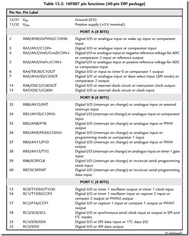
The I/O functions provided by the PIC 16F887 are detailed in Table 13.2. These were mapped against the requirements of the application, and the most convenient grouping was decided, giving the I/O allocation in Table 13.3.

Circuit Description

Figure 13.3 shows the schematic for the temperature controller. Each interface will be described separately. The default internal 4 MHz clock is used, to give a convenient instruction execution time, although no timing critical operations are required in this application.

Analogue Inputs

The four temperature sensors are connected to port A, with four pots providing dummy inputs. It is expected that standard calibrated sensors (LM35 or similar) with an output of 10 mV/oC will be used (0oC ¼ 0 mV). The controller is designed to operate at up to 50oC, at which temperature the sensor output is 500 mV. This low voltage is acceptable if the sensors are not connected on long leads, which could pick up electrical interference. For more remote operation, a dc amplifier should be used at the sensor end of the connection to increase the voltage to, say, 5.00 V at 50oC, and the analogue-to-digital converter (ADC) rescaled accordingly. Screened leads should also be used. The inputs are protected from noise and
PIC Microcontrollers-1317

PIC Microcontrollers-1318

overvoltage by a 1k/1nF low pass filter; the input impedance at the ADC is high enough for this to have a negligible effect on the input voltage measurement.

The ADC normally operates at 10-bit resolution, giving output values in the range 0e1023. It needs reference voltages to set the maximum and minimum values for the input conversion.

These can be provided internally as VDD and VSS (supply values), but VDD does not give a convenient conversion factor. Therefore, an external reference value was provided from a

PIC Microcontrollers-1319

PIC Microcontrollers-1320

2.7 V Zener diode and potential divider, giving Vrefþ adjusted to 2.048 V. This gives a conversion factor of 2048/1024 ¼ 2 mV per bit. To simplify the software, and to cover the correct range, only the low 8 bits of the ADC result will be used in the test program, with a maximum value of 255. At 50oC, the input will be 500 mV/2 mV ¼ 250, giving a resolution of 0.2oC per bit. The test pots allow the input to set manually, to check the operation of the software without having to heat and cool the target system. These can be switched in and out as required via a bank of dual in-line package (DIP) switches.

Outputs

Two types of output device are provided: relay and FET. The relay allows the load circuit to be isolated (electrically separate) from the controller. The external circuit operates with its own supply, so the load (heater in this case) can be powered from a single or three-phase supply. The relay is easy to use, but its changeover is relatively slow, and the contacts may wear out in time. The FET interface is more reliable, as it is solid state. The disadvantage in this design is that the load has to operate from the same supply as the FET, the 5 V board supply. It also does not provide full electrical isolation between the controller and the load. However, the FET interface can be switched at high frequency, allowing PWM speed control, and could be modified for isolated operation. All the outputs include an on-board status light-emitting diode (LED).

Keypad

The 12-button keypad allows the user to input the required temperature and other operating parameters as required by the application program. The target temperature, upper and lower limits, alarm levels and so on would be input as two digits. The keypad is simply a set of switches connected in a row and column arrangement, and accessed by a scanning routine. If the row inputs (A, B, C, D) are all set high initially, and no button is pressed, all the column outputs (1, 2, 3) will be high (pulled up to 5 V). A ‘0’ is then output on each row in turn, and, if a button is pressed, that ‘0’ will appear at the column output and can be detected by the MCU. The combination of the active row and column identifies the key.

Display

A seven-segment display is used, as it is relatively easy to drive compared with the liquid crystal display (LCD), and is self-illuminating. The encoding has been covered in Chapter 10; a look-up table (Table 10.2) provides the output combination for each displayed digit. In this case, two digits are required, but they can both be operated from the same set of outputs by multiplexing. The digits are switched on alternately via Q1 and Q2, at a rate that is fast enough for the digits to appear to be on at the same time, albeit at reduced brightness. Since this effectively halves the average current, the current limiting resistors otherwise needed in the display outputs are unnecessary. Since the switching transistor is acting as a constant current source, and this current will be shared among those segments that are lit, there may be some variation in brightness depending on the digit displayed. This could be improved by using a constant voltage source to control the common terminal current.

Other Interfaces

A buzzer is fitted to provide an audible alarm output. This can be used to signal system failure or, for example, the temperature being too low for too long. Audible feedback from keystrokes is also desirable. A manual reset is provided, so that the program can be restarted without powering down. This will be useful for testing as well as in normal operation. In-circuit programming and debugging are provided via the ICPD connector. An ICD module must be connected between the host PC and the application board.


More Control Systems:Control Technologies

Control Technologies

Microprocessors and microcontrollers are part of a wide range of technologies used in control systems. These include:

• Electromechanical relays

• Programmable logic controllers

• Microcontroller-based boards

• Dedicated microprocessor designs

• PC-based controllers

• Networked control systems.

To complete an overview of controllers, and to allow comparison with PIC microcontroller- based systems, the essential features of these are outlined below.

Electromechanical Control

A familiar example of an electromechanical sequence controller is found in traditional domestic washing machines (non-digital types). A motorized rotary switch slowly operates multiple contacts in the required sequence to open valves (filling), and switch on motors (washing, spinning and pumping) and heaters. Switched sensors (level, temperature) and safety interlocks (door switch) are connected to the same rotor. In this way, purely electromechanical components can be used to make a robust sequence controller, where the environment is hostile to delicate electronics. However, switches and relays are inherently unreliable because of the moving parts and wear on the contacts due to arcing and mechanical forces.


More Control Systems:Other Microcontrollers

Other Microcontrollers

The PIC currently dominates the 8-bit microcontroller market, but a comparison with other controllers is still useful, particularly as the alternatives are generally based on historically significant conventional architectures using complex instruction sets, which provide a useful contrast with the PIC reduced instruction set computing (RISC) architecture.

Intel® 8051 Microcontroller

The Intel PC architecture has dominated the desktop/laptop computer market for many years, and the first widely used general purpose microcontroller was based on this architecture. First introduced in 1980, the Intel 8051 was derived from the then standard PC microprocessor, the 8086. As can be seen in the block diagram (Figure 14.1), the original design had multiple parallel ports, timers and interrupts, and a serial port. The 8051 can be used as a conventional processor, as well as a microcontroller. It can access external memory using port 0 and port 2, which act as multiplexed data and address lines. Some of port 1 and port 3 pins also have a dual purpose, providing connections to the timers, serial port and interrupts. The program memory was erasable programmable read-only memory (EPROM), which had to be erased under ultraviolet light and reprogrammed out of circuit.

The 8051 had a conventional architecture, where the same data bus was used to transfer the program code and the internal data. This makes it inherently slower than the PIC Harvard architecture, which has a separate program and data paths operating concurrently. The 8051 also had a complex instruction set (CISC), which provided more options when programming, but reduced execution speed.

Atmel® AVR Microcontrollers

European manufacturer Atmel offers a range of CISC microcontrollers derived from the 8051 architecture and instruction set. The AT89 family are updated 8051 type MCUs. The AVR

PIC Microcontrollers-1336

range includes 8-bit ATtiny and ATmega devices, and 32-bit AT32 devices. The AT91SAM group are also 32-bit MCUs, but are based on the high-performance ARM architecture.

The internal architecture of a representative chip, the ATtiny20 MCU, is shown in Figure 14.2. The program execution section is similar to the PIC, in that it has a separate instruction bus (Harvard architecture). It also uses a two-stage pipeline, overlapping the fetch and execution cycles. It can therefore execute instructions in one clock cycle, at a maximum clock rate of 12 MHz. It has a similar range of features to the equivalent PIC, that is, an 8-bit and 16-bit timer, serial ports and eight multiplexed 10-bit analogue-to-digital converter (ADC) inputs.

Unlike the PIC, the AVR chip has 16 general purpose registers that contain the current data, compared with the single working register of the PIC. In addition, it has a separate random access memory (RAM) block for data storage, whereas the PIC has a single integrated RAM block containing special function registers (SFRs) and general purpose registers (GPRs). The timers and other SFRs are addressed explicitly in the instruction set rather than as RAM addresses. The stack is implemented as a selected set of RAM locations, making it more

PIC Microcontrollers-1337

flexible in operation but less well protected from corruption by incorrect code. The AVR also incorporates multiple interrupt vectors.

The instruction set is more extensive, comprising 54 instructions with multiple addressing modes. For example, there are several conditional branching instructions, and data movement requires different instructions for load (LD, LDI, LDS), store (ST, STI), move (MOV), input (IN) and output (OUT). This provides some advantages to the experienced programmer who can make best use of the available options, but is more complex to learn initially.

Other Microcontrollers

At the time of writing ST Microelectronics produces a range of microcontrollers with similar features to the PIC16, but with a complex instruction set and conventional architecture.

Freescale Semiconductor Inc. offers a range of microcontrollers based on the architecture and instruction set of the standard Motorola 68000 microprocessor. The current offering concentrates on high-end microcontrollers with 16- and 32-bit cores. Similarly, Texas Instruments Inc. and NXP Semiconductors NV (formerly a division of Philips) offer a power MCU range, including the ARM/CortexM3 32-bit MCUs running at 50 MHz.


More PIC Applications:PIC C Programming

PIC C Programming

For those readers unfamiliar with C programming, a simple example is shown in Program 13.3. The program will give the same output as BIN1.ASM assembly language program. The program must be converted to PIC 16-bit machine code using the MPLAB C18 Compiler,

PIC Microcontrollers-1334

PIC Microcontrollers-1335

which is supplied as an add-on to the development system. This compiler recognizes ANSI (American National Standards Institute) C, the standard syntax for microcontrollers. The C compiler must be selected in the development mode dialogue when building the application.

The main elements of the program are as follows:

/* comment */

Comments in C source code are enclosed between /* and */ and can be run over several lines. A semicolon is used in assembler.

#include<p18f4580.h>

The ‘include’ is a compiler directive that calls up a header file named ‘p18f4580.h’, which has the same function as the include file in assembler, in that it contains predefined register labels for that particular processor and the corresponding addresses.

int counter

This assigns a label to a register and declares that it will store an integer, or whole number. A standard integer in C is stored as a 16-bit number, requiring two data random access memory (RAM) general purpose register (GPR) locations. EQU provides the equivalent operation in assembler.

void main(void)

This rather peculiar syntax simply indicates, as far as we are concerned here, the start of the main program sequence. The following brace (curly bracket) starts the main program block, with a corresponding brace at the end. These are lined up in the same column and the main program tabbed in between them, so that they can be matched up correctly.

counter ¼ 0;

A value of 0 is initially placed in the variable location (low byte). The equivalent in assembler is MOVLW, followed by MOVWF.

TRISB ¼ 0;

A value 0 is loaded into the data direction register of port B to initialize the port bits for output to the LEDs.

while(1)

This starts a loop, which will run endlessly. A condition is placed in the brackets that control the loop. For example, the statement could read ‘while(count<256)’, in which case the following group of statements within the curly brackets (braces) would execute 255 times, counting up to the maximum binary value and stopping. The value 1 means the condition is ‘always true’, so the loop is endless, until reset. This translates into GOTO in assembler, with DECFSZ providing the conditional test.

PORTB ¼ counter;

The value in counter is copied to port B data register for display on the LEDs (assembler equivalent: MOVxx).

counterþþ;

The variable value is incremented each time the loop is executed. This causes the output to be incremented the next time (assembler equivalent: INCF).

Delay10KTCY(100);

This calls a predefined block of code, which provides a delay, so that the LED output changes are visible. At a maximum clock rate, the processor instruction cycle time is 0.1 ms, so the delay works out to 0.1 s (10 000 x 100 cycles). The overall count cycle will then take 25.6 s. The delay function is an example of a function call, corresponding to a subroutine in assembler. We know that this is implemented in assembler as a software delay loop or hardware timer operation.

The layout of the program, with tabs, is important for understanding the program and checking the syntax if there are logical errors. However, the layout does not affect the program function,

only the sequence of characters. Nevertheless, the statements must be all on one line; line returns are not allowed within a statement.

Each complete statement is terminated with a semicolon. Note that some are not complete in themselves, and do not have a semicolon. For example, ‘while(1)’ is not complete without the loop statements, or at least the pair of braces. The close brace terminates the ‘while’

statement. The whole of the main loop, and any functional subblock, must be enclosed between braces.


Hardware Prototyping:Program SCALE1

Program SCALE1

This program will output a musical scale of eight tones. The frequencies for a musical scale from middle C upwards are 262, 294, 330, 349, 392, 440, 494 and 523 Hz. These can be

PIC Microcontrollers-1269

PIC Microcontrollers-1270

translated into a table of delay counts which give the required tone period, since period T ¼ 1/f (s), where f ¼ frequency (Hz). The buzzer on the DIZI board is driven from RB0, so this needs to be toggled at a rate determined by the frequency of each tone. We therefore need to use a counter register or the hardware timer to provide a delay corresponding to half the period of each tone. We have previously seen how to calculate the delay time for a loop. Using a formula for the count value derived from this analysis, figures were calculated for a half cycle of each tone, which were then placed in the data table in SCALE1.ASM. To keep the program simple, each tone will be output for 255 cycles, so we will use another register to count the number of cycles competed during each tone. The scale will then be played over a period of about 5 s. The table of values can later be modified to play a tune in the doorbell program.

Instead of a flowchart, the SCALE1 program source code listing (Program 10.3) has been annotated with arrows to show the execution sequence. This informal method of analysis

PIC Microcontrollers-1271

PIC Microcontrollers-1272

can be used to check the program logic before simulation. The eight tone frequencies are controlled by the value of ‘HalfT’, obtained from the program data table at ‘getdel’. ‘HalfT’ is a counter value, which will give a delay corresponding to half a cycle of the frequency required when the chip is clocked at 4 MHz. The eight tones are selected in turn by the

value of ‘TonNum’, which is initialized to 8. This is used as the program counter offset in the data table fetch operation. It is decremented in the main loop after each tone has finished to select the next. The ‘HalfT’ values are thus selected from the bottom of the table upwards.

The tone is generated in the routine ‘note’, where RB0 is set high, the delay using ‘HalfT’ runs, RB0 is cleared, and the second half cycle delay executed. No OPeration instructions (NOP) have been inserted to equalize the duration of each half cycle. RB0 is toggled 255 times using the ‘Count’ register, which gives a duration of around half a second, depending on which tone is being generated (the lower frequencies are output for longer). The main loop thus selects each of the eight values of ‘HalfT’ in turn, and outputs 255 cycles of each tone.


More PIC Applications:Advantages of C Programming

Advantages of C Programming

The C compiler converts the program into PIC 16-bit machine code. Most of these C statements translate into more than one machine code instruction. This can be confirmed by studying the list file, which is produced by disassembling the machine code.

The pseudocode for the temperature controller above (Program 13.2) can probably be more easily translated into C than assembly language. For example, the conditional control operations defined using IF.THEN statements will translate directly, whereas, in assembler, they have to be implemented by suitable combinations of ‘Bit Test and Skip’ with ‘Goto’ or ‘Call’. The comparison of the ‘average temperature’ with the set values can be done in one statement in C, but in assembler needs a subtract or compare prior to a bit test, which is much more complicated. On the other hand, checking bit inputs is not as easy in C as in assembler, as ANSI C contains no individual bit operations. Bit status in a register has to be checked by using a logical or numerical range check.

There are many references on C programming. To program a microcontroller in C, only the basic set of statements and simple data structures will probably be needed, so if the reader has some knowledge of C already, using it to develop PIC applications should not be too difficult. For further details, see Programming 8-Bit PIC Microcontrollers in C with Interactive Hardware Simulation by this author (Newnes 2008). This uses the CCS C compiler, which has a complete set of ready-made functions that simplify the C code, especially I/O handling and mathematical functions.

1. (a) What interfacing modifications are recommended for the LM35 temperature sensor if the connections are over 1 m long? (4)

(b) For the TEMCON2 system, calculate the output of the LM35 sensor at 25oC, and

the decimal value that would be found in the ADRESL on completion of an A/D conversion of this input, if the result is right justified. (4)

2. State one advantage of (a) the relay output and (b) the FET output as used in the temperature controller. (4)

3. Describe briefly how a multiplexed seven-segment LED display works, and its advantage in terms of I/O requirements. (4)

4. Suggest two reasons why the PIC 16F818 would be preferred over the 16F84A in a temperature control application. (4)

5. Compare PIC assembler and ANSI C programming, outlining the advantages of each. (5)

1. Devise an alternative keypad scanning routine to that in Program 13.1 using the rotate instruction, such that the binary value for the keys 0e9 are stored in a suitable register.

2. Design and implement the fully functional program for the temperature controller based on the pseudocode provided in Program 13.2. The user will enter an upper and lower temperature limit, and set the controller to run mode, where the outputs are operated to maintain the temperature between those limits. The system should tolerate a fault in one sensor which puts the output outside the normal operating range. Develop a full design and performance specification for the controller. Test by simulation.

3. Design a temperature-controlled enclosure with heaters, fan and vent, which will allow a fully functioning temperature control program to be tested. Investigate the design of an interface for the fan sensor, so that the fan speed could be controlled by PWM with feedback. Investigate the set-up required to use the PWM output of the 16F887, and redesign the hardware to connect the fan to a PWM output.

4. Implement the minimal temperature controller proposed above using the 12F675 chip, operating as specified in Table 13.1. Create a schematic, simulate the application (interactively if possible), design a layout, implement and test.

5. Study relevant C programming references and the Microchip manual ‘MPLAB C18 C Compiler, Getting Started’, and modify the program BIN1.C such that the output can be stopped, started and reset by push-button inputs at RA0 and RA1. Why is reading the inputs more difficult in C?


More PIC Applications:16F818 Temperature Controller

16F818 Temperature Controller

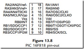
The PIC 16F818 is a replacement part for the 16F84A. It has a compatible pin-out (Figure 13.8), and additional features at a lower cost. Sixteen I/O pins are available, including five analogue inputs. It has 1k words of program memory; if extra memory is needed, the 16F819 has the same features but 2k program memory. As usual, each pin has multiple functions, other than the two supply pins. Analogue inputs can be selected on RA0eRA4, or external reference voltages. There is a capture, compare and PWM (CCP) module and a synchronous serial port offering serial peripheral interface (SPI) or inter-integrated circuit (I2C) modes. Other special features are a variety of power-saving modes in addition to the usual ‘sleep’, an internal oscillator which obviates the need for external clock components, and in-circuit programming and debugging.

This chip can be used in the temperature controller if the keyboard is eliminated, and the set temperature is input from a pot via one of the analogue inputs (Figure 13.9). A fixed control range might be acceptable, or other analogue inputs assigned for setting maximum and

PIC Microcontrollers-1330

minimum temperatures. The display digit selection can be reconfigured to use only one output, or binary coded decimal (BCD) displays used which need only four outputs each. The application then only needs 16 I/O pins. Operating data could be transferred via the serial interface if the display is omitted (RB1, RB2 and RB4).


PIC Motor Applications:Motor Application Board MOT2

Motor Application Board MOT2

We will investigate these ideas via a general purpose motor test board design, MOT2, which can control a dc motor requiring up to 30 A drive current. This is provided by a full bridge driver that allows bidirectional speed and position control with pulse feedback (servo motor). MOT2 is based on the PIC 16F690 (as used in the LPC demo board). A block diagram is shown in Figure 11.2 and a circuit schematic in Figure 11.3.

A variety of motor control operations can be demonstrated using this system:

• Motor On/Off

• Motor Forward/Reverse

• Open/Closed Loop Position Control

• Open/Closed Loop Speed Control.

Command inputs can be received from an 8-bit switch bank, a remote 8-bit master controller, two push buttons, or from the analogue inputs or serial ports. The motor can be turned in either direction via a full bridge driver, providing position and speed control. Pulse width modulation (see Chapter 8) will be used to control the speed. The shaft speed and position are monitored by a shaft encoder, which has three outputs, but only the index output (one pulse per revolution) is connected in the initial design. In the simulation schematic, the motor and encoder are integrated into a single servo motor model, DCM.

PIC Microcontrollers-1285

Motor Drive

A 6 V permanent magnet motor is used since it will run from the same 5 V supply as the PIC. However, a large decoupling capacitor (C4) should be fitted because the motor will generate a lot of noise on the supply, particularly when it switches off. The motor current direction, forward or reverse, is controlled by switching on two of the four MOSFETs from RA4 or RA5. Q1 and Q3 are switched on if RA4 output goes high (motor forward), and Q2 and Q4 if RA5 goes high (motor reverse). Q1 and Q2 switch on when the gate is high (N-FET), but Q3 and Q4 switch on when the gate is low (P-FET), so an inverting bipolar stage is needed on each gate. The current flows diagonally through the bridge and motor to drive it in either direction. The bridge is rated at 30 A, so a range of small to medium dc motors could be driven successfully. In the simulation, the motor characteristics can be adjusted to represent different motors: nominal voltage, coil resistance, coil inductance, zero load rpm, effective mass of the motor and load, and the number of encoder pulses per revolution.

Output Sensor

The rotary encoder represented in the simulation circuit schematic has three outputs. Two have the same number of slots per revolution (adjustable in simulation to represent a range of encoders, default 24), but they are offset by half a slot so that the direction of rotation can be detected from the phase difference in the output signals. The third output generates an index signal once per revolution, which can be used to generate an absolute initial position, or to measure the speed as time per revolution. In hardware, an opto-sensor containing a light- emitting diode (LED) and photodetector can be mounted either side of a perforated wheel attached to the motor shaft. This allows the light to pass through holes or slots causing digital pulses to be output from the sensor via a built-in amplifier, allowing the motor speed or position to be monitored by the controller. The simplest type can have a single slot producing one pulse per revolution. Alternatively, the sensor can work by reflection from a shaft surface, or magnetically. The index output on the simulated servo in Figure 11.3 is connected to the Timer0 (T0CKI) input of the PIC, so that the shaft revolutions can be counted. Alternatively, the pulse interval can be measured using timer mode, if that will produce a more accurate measurement. The pulse may also be used to trigger a Timer0 interrupt.

Switched Inputs

The control program can use the push buttons (S1, S2) connected to RB6 and RB7 to stop, start, or change speed or direction. The binary input switches could be used to select the speed or position. Alternatively, a remotely generated digital control code can be applied to the digital input connector pins (J2) from a master controller, which could be operating a number of motors in a robot system or machine tool. In this case, part of the digital input would be a motor select code, and part would be a position or speed command. Serial commands could also be used, with the port B pins reassigned for this purpose (see Section 12.4). If the parallel input is removed from the circuit, a smaller, cheaper PIC 12FXXX series device could be used instead.

These have six input/output (I/O) pins, so there would be three inputs available with which to control the motor speed, position and/or direction. Analogue inputs are also available, if the motor needs to be voltage controlled.

Analogue Input

The analogue input could be used to receive a voltage that sets the speed or position of the motor. For example, a position servo may use a potentiometer to provide position feedback to the controller, or a temperature sensor might control the speed of a fan. The analogue-to-digital converter (ADC) must be initialized to suit, in this case using the internal supply reference to set the range. For test purposes, a pot is connected to AN10, to provide a dummy analogue input. If the jumper is closed, AN11 can be used to monitor the motor drive current as a voltage across a 0R1 current sensing resistor connected in the common arm of the bridge (100 mV/A). This can be used as a feedback signal or to shut down the output if the motor current is too high. External analogue inputs can be connected at J1.

The default internal clock frequency of the PIC 16F690 is 4 MHz to give an instruction cycle time of 1 ms. The internal clock mode needs to be selected in the configuration word at the top of the program, along with the power-up timer and MCLR enable (00E4h). MCLR is controlled from the programmer during testing, but a reset button is also provided on board. The power-on timer should be enabled during programming to ensure a reliable start. The motor drive will need an external power supply providing sufficient current for the motor connected, so the supply from the programming connector may need to be disconnected at JP2 while programming.


More PIC Applications:12F675 Temperature Controller and PIC C Programming

12F675 Temperature Controller

The 10 and 12 series of PIC mini-chips offer a minimal set of features in eight-pin packages. The pin-out for the 12F675 illustrates the point (Figure 13.10). It can be configured with six plain digital I/O pins, but also offers two timers, an analogue comparator or four analogue input channels. The 12F629 is the same, except that it does not include the ADC and is therefore a little cheaper. An internal oscillator and in-circuit programming are also available.

A temperature controller could be implemented using this chip if only two analogue inputs are used (Figure 13.11). It could operate with a fixed set temperature, or another analogue input could be used as a set temperature input. With no display, a dial on the set temperature pot may be useful.

PIC C Programming

The 18 series are the most powerful of the 8-bit PIC microcontrollers. The group offers a large selection of different combinations of advanced 8-bit features, and the larger memory size means that ‘C’ can be used for application programming, instead of assembler. The instruction set of 75 16-bit instructions is designed to support this option. New low-power consumption devices are being added to this range all the time.

PIC Microcontrollers-1331

Comparison of 16 and 18 Series PICs

A small selection of the available 18F devices is included in Table 12.2. The architecture is somewhat more complex than the 14-bit devices, with extra blocks for multiplication,

a hardware data table access, additional file select registers and other advanced features. However, the data bus is still 8 bits. Taking the 18F4580 as an example, in terms of peripheral features it is comparable to the 16F887 described in Section 13.1, so a comparison of the two devices will be made to illustrate the differences and similarities of the two groups (Table 13.4).

As can be seen, the 18 series device has some advantages: 40 MHz clock rate, 16k program memory and more data memory. However, bear in mind that a program written in C will not be as code efficient as an assembly language equivalent, so these advantages may or may not translate into faster performance, depending on the application and the way that it is structured. The main advantage is that more complex operations, such as mathematical functions, are easier to program in C. For example, the conversion of binary temperature readings to two-digit BCD will be much easier in the temperature controller above. The 18 series PIC has a richer instruction set, including instructions such as multiply, compare and skip, table read, conditional branch and move directly between registers, so still has advantages even when programmed in assembly language.