TIMERS AND COUNTERS:Exercises for Timers and Exercises for Counters

Exercises for Timers

1. Write a program to generate a one minute timer clock with a 0.1 second display and then do the following:

N Check its accuracy with the time site on the Internet.

N Make adjustments to make it accurate to within one second per hour and then per day. Can this be done? Which timer works best? Which timer is the easiest to use for such a task? What are the problems that you identified?

2. Write the preceding program for each of the other two timers.

Exercises for Counters

1. Design and make a tachometer for small model aircraft engines. Make the range

between 5 rev per second to 50,000 rev per minute displayed on the LCD in real time.

2. Design and build a thermometer based on the changes in frequency exhibited by a 555 timer circuit being controlled by a thermistor. Calibrate the thermometer with a lookup table. If you are not familiar with the use of lookup tables, research on the Internet so you can understand how to use them. They are very useful devices at the level that we are working.


TIMERS AND COUNTERS:COUNTERS

COUNTERS

Of the three timers in the 16F877A, only Timer0 (an 8-bit timer) and Timer1 (the 16-bit timer) can be used as counters. Timer2 does not have a counter input line. Generally speaking this makes Timer0 suitable for use with small counts and rapid interrupts and Timer1 suitable for larger counts.

HOW DOES A COUNTER WORK?

The operation of a counter is similar to the operation of a timer except that instead of getting its count from an internal clock or oscillator, the counter gets its signals from an outside source. This means we have to do the following to use a counter:

N Decide which counter (timer) to use.

N Tell the counter where the signal is coming from.

N Tell it whether to count on a rising or falling edge of the signal.

N Decide what target count we are looking for, if applicable.

N Tell the counter where to start counting (because the interrupt will occur when the counter gets full).

N Decide whether we will need to scale the count by setting the scaler(s).

Once you start a counter, the counting continues until you deactivate it. There is no way to stop it or any purpose in doing so. It will reset if the MCU is reset, and it can

be reset by writing to it. The rest has to do with knowing what bits to set in the control registers to get the counters to operate in the way we want them to.

USING TIMER0 AS A COUNTER

The three registers used to control the operation of the Timer0 module are TMR0, INTCON, and OPTION_REG. The interrupt control register is INTCON. See the data sheet.

Note Though often called Timer0 and referred to as Timer0 here and in the data sheet, the real designation of this timer address is TMR0.

This counter has the following properties:

N 8-bit timer/counter.

N Readable and writable.

N 8-bit software programmable pre-scaler.

N Internal or external clock select.

N Interrupt on overflow from FF (hex) to 00 (hex).

N Edge selection available for external clock signal.

N Counter mode is selected by setting OPTION_REG.5=1.

N External input for the timer must come in on PORTA.4 (pin 6 on the PIC).

N The edge direction is selected in OPTION_REG.4 (1=Rising edge).

N The pre-scaler is assigned with bits 0 to 3 of the OPTION_REG register (Chapter 5).

Note The Watchdog Timer cannot use the pre-scaler when the pre-scaler is being used by Timer0.

Since this is an 8-bit counter, it is suited to the counting a small number of counts, but longer counts can be accommodated by creating a routine to keep track of the number of interrupts.

Let us use the counter to count the pulses received from a 42-slot encoder mounted on a small DC motor. This same source will be used later for the Timer1 experiment for comparison between counters. (This motor will also be used later on as the encoded servomotor for the servo control experiments.)

We will set up the LCD display so that we can display certain registers during the operation of the program. We will also set the program up to read the potentiometers so that we can use their values to modify the program as the motor runs. Only POT0 and POT1 are used in this program.

RUNNING SMALL MOTORS-0075

RUNNING SMALL MOTORS-0076

Put these and other values in the program and run the program. See what happens.

USING TIMER1 AS A COUNTER

The operation of Timer1 as a counter is similar to the operation of Timer0. However, because Timer1 is a 16-bit timer, much longer counts can be handled and counts com- ing in at faster rates can be counted. It also means that a lot more can be done in the TimerLoop and BlinkerLoop routines if the program is designed to do so. However, the set up for Timer1 is more complicated because of the more numerous options available.

The differences between the use of the two timers have to do with the setup of the controlling registers. Timer1 is controlled by six registers, compared to the three for Timer0. Timer1’s registers are as follows:

RUNNING SMALL MOTORS-0077

Again, and as always, the frequency of the oscillator is divided by 4 before being fed to the counter when you use the internal clock.

Page 52 of data sheet describes how Timer0 is used with an external clock. Counter mode is selected by setting bit TMR1CS. In this mode, the timer increments on every rising edge of clock input on pin RC1/T1OSI/CCP2, when bit T1OSCEN is set, or on pin RC0/T1OSO/T1CKI, when bit T1OSCEN is cleared.

Three of the pins on the 16F877A can be used as inputs to the Timer1 counter module:

N Pin PORTA.4, the external clock input (pin 6 on the PIC)

N Pin PORTC.0, selected by setting TIOSCEN =1

N Pin PORTC.1, selected by setting TIOSCEN=0

Timer1 is enabled by setting T1CON.0=1. It stops when this bit is turned off or disabled.

The clock that Timer1 will use is selected by T1CON.1. The external clock is selected by setting this to 1. The input for this external clock must be on PORTA.4.

In summary, eight bits in Timer1 control register T1CON, which provides the fol- lowing functions:

N Bit 7: Not used and read as a 0 N Bit 6: Not used and read as a 0 N Bit 5: Input pre-scaler

N Bit 4: Input pre-scaler

N Bit 3: Timer1 oscillator enable

N Bit 2: Timer1 external clock synchronization

N Bit 1: Timer1 clock select

N Bit 0: Timer1 enable

If the interrupts are not going to be used all the other registers can be ignored, and we can set:

T1CON to %00110001

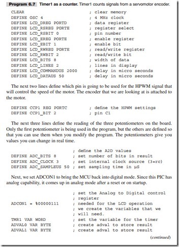
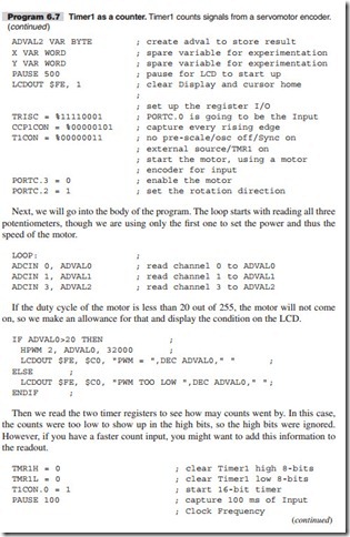
The setting of these bits is described in detail in Chapter 5 of the data sheet. Program 6.7 reflects this discussion.

First let us define all the defines that we will need. Here all the defines are included as an example, but not all are needed when using the LAB-X1.
RUNNING SMALL MOTORS-0078

RUNNING SMALL MOTORS-0079

RUNNING SMALL MOTORS-0080


TIMERS AND COUNTERS:TIMER OPERATION CONfiRMATION

TIMER OPERATION CONfiRMATION

To make sure a timer is working, set up a program in which the interrupt routine incre- ments a variable and the main loop displays it. If you see the variable incrementing, the interrupt routine is working.

The speed of the incrementing will give you some idea of the rate at which the interrupts are occurring and will confirm that the interrupts are occurring as fast as you have programmed them to.

Other timer related registers can also be looked at to see what is going on in them by displaying them on the LCD.

Caution Writing to the LCD is time consuming and will slow down the system.


TIMERS AND COUNTERS:PRE-SCALERS AND POST-SCALERS

PRE-SCALERS AND POST-SCALERS

Pre-scalers and post-scalers can be confusing for the beginner. Here is a simple explanation.

A pre-scaler is applied to the system clock and affects the timer by slowing down the system clock as it applies to the timer. Normally the timer is fed by a fourth of the basic clock frequency, which is called Fosc/4. In a system running a 4 MHz, the timer sees a clock running at 1 MHz. If the pre-scaler is set for I:8, the clock will be slowed down by another eight times, and the timer will see a clock at 125 kHz. See Figure 6.2 (for Timer1) in the data sheet to see how this applies to Timer1.

A post-scaler is applied after the timer count exceeds its maximum value, generating an overflow condition. The post-scaler setting determines how may overflows will go by before an interrupt is triggered. If the post-scaler is set for 1:16, the timer will overflow 16 times before an interrupt flag is set. The upper diagram on page 55 (for Timer2) of the data sheet shows this in its diagrammatic form and is worth studying.

All other things being equal, both scalers are used to increase the time between interrupts.

When starting out, just leave the scalers at 1:1 values and nothing will be affected. We will not need them for any of the experiments that we will be doing right away. Once you learn the more sophisticated uses of timers you can play with the values and learn more about how to use them. The primary use is in creating accurate timing intervals for communications and so on, because no external routines are necessary when this is done with scalers. Everything becomes internal to the PIC and is therefore not affected by external disturbances.

Note Additional information on timer modules is available in The PICmicro Mid-Range MCU Family Reference Book (DS33023).


TIMERS AND COUNTERS:THE WATCHDOG TIMER

THE WATCHDOG TIMER

A Watchdog Timer is a timer that sets an interrupt that tells us that for some reason the program has hung up or otherwise gone awry. As such it is expected that in a prop- erly written and compiled program the Watchdog Timer will never set an interrupt. This is accomplished by resetting the Watchdog Timer every so often in the program. The compiler inserts these instructions automatically into the program if the Watchdog Timer option is selected. However, setting the option does not guarantee that a pro- gram cannot or will not hang up. Software errors and infinite loops that reset the timer within themselves can still cause hang ups.

The Watchdog Timer is scalable. It shares its scaler with Timer0 on an exclusive basis. Either it uses the scaler, or Timer0 uses it. They cannot both use it at the same time. See the discussion under Timer0 in the data sheet for more information (Chapter 5).

Since PICBASIC PRO assumes that the Watchdog Timer will be run with a 1:128 pre-scaler, unwanted Watchdog Timer resets could occur when you assign the pre-scaler to Timer0. If you change the pre-scaler setting in OPTION_REG, you should disable the Watchdog Timer when programming. The Watchdog Timer enable/disable option is found on the configuration screen of your (hardware) programmer’s software.


CONTROLLING THE OUTPUT AND READING THE INPUT:THE LCD DISPLAY

THE LCD DISPLAY

This section describes the use of and interactions with existing hardware connections as they come with the LAB-X1 module. Other wiring schemes can be used with ease as defined in the compiler manual.

The LCD is controlled from PORTD, and all eight bits of this port are connected to the LCD. You therefore have the choice of using only the four high bits as a 4-bit data path for the LCD or using all eight bits. The entire port is also connected to eight of the LEDs on the 10-light LED bar graph. (The two leftmost LEDs in the bar graph are used to indicate that the power to the LAB-X1 is on.) The four high bits, bits D4 to D7, cannot be used for any other purpose if the LCD is being used. The software does not release these four bits automatically after using them to transfer information to the LCD, but you do have the option of saving the value of PORTD before using the LCD and then restoring this value after the LCD has been written to. The complication, of course, is that there will be a short glitch when the LCD is written to, and the use you make of PORTD has to tolerate this discontinuity.

PORTE, which has only three external lines, is dedicated to controlling the information transfer to the LCD. These lines can be used for other purposes (analog or digital) if the LCD is not being used.

The LCD provided on the LAB-X1 allows us to display two lines of 20 characters each. Its connections to the microcontroller are shown on the schematic provided with the LAB-X1 and are as shown in Figure 5.3.

RUNNING SMALL MOTORS-0023

Figure 5.3 is an easy to comprehend schematic diagram that shows the lines between the microcontroller and the display module. The other wiring is still in place, but it has been suppressed so we can concentrate on the LCD connections.

In Figure 5.3 we see that the LCD uses all the lines available on ports D and E. All of PORTD is used as the port the data will be put on, and PORTE, which has only three lines, is used to control data transfer to the LCD. We also know from looking at the full schematics provided with the LAB-X1 that all of PORTD is also connected to the LED bar graph. This does not affect the programming of the LCD and we will ignore this for now. You will, however, notice that the LEDs in the bar graph go on and off as programs run because we will be manipulating the data on these lines (D0 to D7). It is also possible to control the LCD with just the four high bits of PORTD, and we will use the scheme for most of the programs in this book. See the PBP manual for more information on how this is done.

Let us write the ubiquitous “Hello World” program for the LCD as our first exercise in programming the LCD. Once we know how to do that, we can basically write what- ever we want to the LCD display and whenever we want to.

Before we can write to the LCD we have to define how the LCD is connected to the MCU. Also, since the 16F877A has some analog capabilities, it always starts up and resets in its analog mode, and it has to be put into digital mode for (at least) PORTE before we can use any of the digital properties of the affected ports (A and E).

The compiler manual says that we have to specify the location of both the LCD data and the LCD control lines that connect it to the system so that the compiler can address the device properly. Doing so allows us to place the LCD where convenient for us, in memory (the I/O lines), when we design our own devices, and the compiler will be able to address the LCD. The ports and lines used are specified in DEFINE statements that must be executed early in the program before the LCD is addressed.

Note When you are designing your own devices it will be an advantage to place your LCD at the same memory locations used by the LAB-X1 so that your programs will run on the LAB-X1 for testing purposes, should you get into trouble. Being able to run the program on the LAB-X1 will let you know if it is a hardware or a software problem. All the devices I built used the same addresses as the LAB-X1 for the LCD, and this is reflected in the programs listings throughout this book.

For the LCD display registers, on the LAB-X1, the DEFINE statements are as indi- cated in Program 5.4.

RUNNING SMALL MOTORS-0024

RUNNING SMALL MOTORS-0025

Program 5.4 demonstrates the most elementary control over output to the LCD display. Variations of these lines of code will be used to write to the LCD in all our programs. (We will always use these addresses but when the reader writes his or her programs they can be at any suitable address.) Be sure to include the PAUSE 500 instruction in all your programs to allow the LCD enough time to initialize.

Not all the preceding DEFINE statements are needed on the LAB-X1, and you will notice this in some of the sample programs in this book, but when you build your own devices, you will need to include them all to make sure that nothing has been omitted.

ADCON1 = Analog to Digital CONtrol register #1.

The ADCON1=%00000111 statement, or one like it, is needed for our use of the 16F877A because any PIC MCU processor that has any analog capabilities comes up in the analog mode on reset and startup. In the analog mode all the lines of the PIC that have analog capabilities are set to the analog mode. This particular instruc- tion puts all the analog pins on ports A and E into the digital mode. Since we need only PORTE and PORTD for controlling the LCD, none of PORTA needs to be in digital mode. I am showing %00000111 because all the examples provided by MicroEngineering Labs use this value. See the data sheet for more detailed informa- tion. (The use of this register is explained in Table 9-8 on using the LCD.) If you want to turn just the three available lines on PORTE to digital mode, you can use any binary value from 010 to 111 inclusive.

The control of the A to D conversion capability is managed by the four low bits of ADCON1. For our purposes, bit 0 and bit 3 are not relevant.

Note Much of the information in this chapter can be found on page 126 in Section 11 Analog to Digital Converter (A/D) Module of the data sheet.

The following lists how the four least significant bits in register ADCON1 are used to manage the A to D setting of the three bits of PORTE and five relevant bits of PORTA. (We are setting them all except PORTA.4 to digital.) Bit 0 is not relevant to the LCD operation (it is a “don’t care” bit).

N Bit 1 and 2 must be set to 1 to make the two ports (A and E) digital

N Bit 3 is not relevant to the LCD operation (it too is a “don’t care” bit.)

RUNNING SMALL MOTORS-0026


TIMERS AND COUNTERS

If you have no knowledge about timers, you should read this chapter a few times. However, there is some repetition in the other chapters to allow each part of the book to stand as an independent resource.

Most users will find that using the timers and the counters is the hardest part of learning how to use PIC microcontrollers. With this in mind, we will proceed in a step-by-step manner and build up the programs in pieces that are easier to digest. Once you get comfortable with their setup procedures, you will find that timers and counters are not so intimidating.

We will cover timers and counters separately. Counters are essentially timers that get their clock input from an outside source. There are two counters in the 16F877A, and they are associated with Timer0 and Timer1. Timer2 cannot be used as a counter because there is no input line (internal or external) for this particular counter.

Note The clock frequency utilized by the timers is a fourth of the oscillator fre- quency. This is the frequency of the instruction clock. This means that the counters are affected by every fourth count of the main oscillator. The frequency is referred to as Fosc/4 in the data sheet. When responding to an external clock signal the response is to the actual frequency of the external input. (For now, we’ll run the LAB-X1 and thus all the programs at 4 MHz, so all the timers will be getting internal inputs at 1 MHz.)

Caution The PICBASIC PRO compiler generates code that does not respond to interrupts while a compiled instruction is being executed. Therefore long pauses (long enough to lose an interrupt signal, which depends on how the timer is set up) can lead to lost interrupts if more than one interrupt occurs during the pause. Since interrupts are used for the express purpose of handling critical response/ timing needs, this is most undesirable. Therefore, PAUSE commands should be used with care. The program samples provided in this chapter give examples of how to use short pauses in loops to get a long pause.


CONTROLLING THE OUTPUT AND READING THE INPUT:EXERCISES

EXERCISES

Answers to these problems are not provided.

Since this is really all about input and output, a comprehensive set of exercises that focus specifically on input and output have been provided. We need to be completely comfortable with these I/O functions before we start on running motors, so you are encouraged to expand on these exercises on your own. These and similar techniques

will be used to control and respond to all the ancillary devices that we will use with our motors.

LED EXERCISES: CONTROLLING

THE LIGHT EMITTING DIODES (LEDS)

We will learn more about controlling the output from the LAB-X1 by writing a series of increasingly complicated programs that will control the ten-segment LED IC pro- vided on the LAB-X1. In these exercises we are controlling the LEDs, but the control strategies developed will apply to any kind of “on/off” devices that we will connect to the LAB-X1 or to any other device that we may design.

1. One at a time, light the eight LEDs on the right till they are all lit, and then turn them off one at a time. Time delay between actions is to be as close to one tenth of a second as you can get it.

2. Modify the preceding program so that the delay time is controlled by the top- most potentiometer on the LAB-X1. The time is to vary from 10 milliseconds to 200 milliseconds—no less, no more.

3. Write a program that will vary the glow on the rightmost LED from fully off to fully on once a second. Program the second LED to go dark and bright exactly 180 degrees out of phase with the first LED so that as one LED is getting brighter, the other LED gets dimmer, and vice versa.

4. Write a program that flashes the four leftmost LEDs on and off every 0.25 seconds and cycles the four LEDs on the right through a bright/dim cycle every two seconds.

5. Write a program that flashes the first LED 10 times a second, flashes the second one 9 times a second, and flashes the third LED whenever both LEDs are on at the same time. Display how many times the third LED has blinked on the LCD display. (Timing can be approximate but has to have a common divider so the third LED will give the beat frequency.)

LIQUID CRYSTAL DISPLAY EXERCISES: CONTROLLING THE LCD

The addresses of the memory locations used by the LCD have already been fixed, as has the instruction set that we use to write to the LCD. The description of the Hitachi HD44780U (LCD-II) controller instruction set, as well as its electronic characteristics, are given in the data sheet provided for the display. Here we will list only the codes that apply to our immediate use of the device.

There are two types of commands that can be sent to the display: the control codes and the set of actual characters to be displayed. Both uppercase and lowercase char- acters are supported, as are a number of special and graphic characters. The control codes allow you to control the display and set the position of the cursor and so on.

Each control code has to be preceded by decimal 254 or HEX$FE. (The controller also supports the display of a set of Japanese characters, which are not of interest to us.)

Command codes for the following actions are provided along with others. Go to the data sheet for the controller to learn what all these command codes are.

N Clear the LCD

N Return home

N Go to beginning of line 1

N Go to beginning of line 2

N Go to a specific position on line 1 N Go to a specific position on line 2 N Show the cursor

N Hide the cursor

N Use an underline cursor

N Turn on cursor blink

N Move cursor right one position

N Move cursor left one position

There are still other commands that you will discover in the data sheet. There are more memory locations within the LCD, and there are invisible locations beyond the end of the visible 20 characters.

It is also possible to design your own font for use with this particular display; all the information you need to do so is in the Hitachi HD44780U book/data sheet.

1. Write a program to put the 26 letters of the alphabet and the 10 numerals in the 40 spaces that are available on the display. Put four spaces between the numbers and the alphabet to fill in the four remaining spaces. Once all the characters have been entered, scroll the 40 characters back and forth endlessly though the two lines of the display.

2. Write a program to bubble the 26 capital letters of the alphabet through the numbers 0 to 9 on line two of the LCD. To do this, first put the numbers on line two. Then “A” takes the place of the “0” and all the numbers move over. Then the “A” takes the place of the “1” and the “0” moves to position 1. Then the “A” moves into place of the “2,” and so on till it gets past the 9. Then the “B” starts its way across the numbers and so on. Loop forever.

3. Write a program to write the numbers 0 to 9 upside down on line 1. Wait one second and then flip the numbers right side up. Loop.

4. Write a program to write “HELLO WORLD” to the display and then change it to lowercase one letter at a time with 50 milliseconds between letters. Wait one second and go back to uppercase one character at a time with negative letters (all dots on the display are reversed to show as dark background with white letters and on to lowercase). Loop.

ADVANCED EXERCISES

These exercises are designed to challenge your programming ability. Again, you will need access to the data sheet for the LC Display.

1. Editor: Write a program that displays 12 random numbers on line 1 of the LCD and displays a cursor that can be moved back and forth across the 20 spaces with poten- tiometer 0. The entire range of the potentiometer must be used to move across the 20 spaces. Allow the keypad to insert numbers 0 to 9 into the position that the cursor is on. Assign a delete switch and an insert space switch on the keyboard. A comprehen- sive number (plus decimal and space) editor is required.

2. Mirror: Write a program that puts a random set of letters and numbers on line 1 and then puts their mirror images on line 2. The mirror is between line 1 and line 2. To do this, you have to learn how to create the upside down numbers from the Hitachi data sheet for the display, and you have to learn how to read what is in the display from the display ROM.

3. Forty characters: The display ROM is capable of storing 40 characters on each line.

Design a program to allow you to scroll back and forth to see all 40 characters on both lines one line at a time. Use two potentiometers for scrolling, one for each line.

4. Four lines: Write a program to display four lines of random data on the LCD and to scroll up and down and side to side to see all four lines in their entirety. You have to store what is lost from the screen before it is lost so that you can re-create it when you need it.

5. Bar graphs: Create a three-bar graph display, with each bar 3 pixels high, that extends across both lines of the LCD. The lengths of the bar graphs are determined by the settings of the three potentiometers and changes as the potentiometers are manipulated.


THE SOFTWARE, COMPILERS, AND EDITORS:PICBASIC PRO COMPILER INSTRUCTION SET

PICBASIC PRO COMPILER INSTRUCTION SET

RUNNING SMALL MOTORS-0012RUNNING SMALL MOTORS-0013RUNNING SMALL MOTORS-0014RUNNING SMALL MOTORS-0015

As you can see from the preceding comparison, the PICBASIC PRO compiler pro- vides a much more comprehensive instruction set and is the compiler of choice for serious development work. The mathematical functions are substantially more powerful.

It is, of course, also possible to program microcontrollers in assembly language and “C” (and other languages), but this book does not cover this programming. There are a number of good books on the subject and some that I looked over are listed in a file on the support web site for this book (www.encodergeek.com) with my comments.

Some educators feel that a junior college-level class on the subject is the best way to learn how to do this and there is some merit to this but for our purposes the PICBASIC PRO compiler will do everything we need.

In addition to the compiler, you need an editor to allow you to write and edit pro- grams with ease. A very adequate editor, the MicroCode Studio editor, is provided as a part of the compiler package. This comprehensive and powerful editor is available on the Internet at no charge from MicroCode Studios. This is a complete editor with no limit on the number of lines of code that you can write. It is fully integrated with the software and hardware provided by microEngineering Labs and is the editor of choice for most users. The free version is limited to compiling programs for just a few microcontrollers, but these include both the 16F877A, 18F4331, and the 16F84A.

The editors available are as follows:

N MicroCode Studio Mecanique’s MicroCode Studio is a powerful, visual Integrated Development Environment (IDE) with In-Circuit Debugging (ICD) capa- bility designed specifically for microEngineering Labs PICBASIC PRO compiler. This software can be downloaded from the Internet at no charge. The only limitation on it is that it allows you to run only one IDE at one time, but that’s not a real handicap at our level of interest. This is the editor that best suits our needs and all programs in this book were written with this editor.

N Proton+ This is a lite basic editor provided by CrownHill. This is a test version of their editor and is limited to 50 lines of code and three processors including the PIC 16F877A. It’s a nice editor but limited in the free version to the 50 lines of code. If you like this editor, you can use this as your main editor and then cut and paste to the MicroCode Studio to compile and run your programs and thus go around the 50-line limit. The native language of this editor is not the same as PicBasic so there are other handicaps to contend with, which are best avoided.

N MicroChip MPLAB This is the software that the maker of the microcontrollers, Microchip Technologies, provided for editing programs written for their PIC series of microcontrollers. It is an assembly level programmer. We are not going to be doing any assembly language programming, but the editor can be useful and you should be aware of its existence.


UNDERSTANDING THE MICROCHIP TECHNOLOGY PIC 16F877A: FEATURES OF THE MCU

UNDERSTANDING THE MICROCHIP TECHNOLOGY PIC 16F877A: FEATURES OF THE MCU

PIC microcontrollers are manufactured by the Microchip Technology Corporation of Chandler, Arizona.

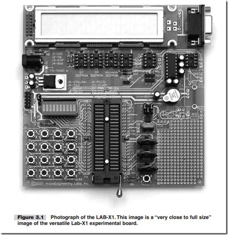
We will be using the recommended 16F877A microcontroller in the LAB-X1 board, see Figure 3.1. Not all the features provided in the 16F877A will be addressed in the exercises to follow, but enough will to give you the confidence and understanding you need to proceed on your own. In more technical terms, this MCU has the following core features (this list was reduced and modified from description by Microchip Technologies):

N High-performance RISC CPU

N Operating speed: DC-20 MHz clock input

N DC-200 ns instruction cycle

N Up to 8K s 14 words of FLASH program memory

N Up to 368 s 8 bytes of data memory (RAM)

N Up to 256 s 8 bytes of EEPROM data memory

N Interrupt capability (internal and external)

N Power-on Reset (POR)

N Power-up Timer (PWRT) and Oscillator Start-up Timer (OST)

N Watchdog Timer (WDT) with its own on-chip RC

N Programmable code-protection

N Power-saving sleep mode

N Selectable oscillator options

RUNNING SMALL MOTORS-0003

N Low-power, high-speed CMOS FLASH/EEPROM technology

N Fully static design

N In-circuit Serial Programming (ICSP) via two pins N Single 5V In-Circuit Serial Programming capability N In-Circuit debugging via two pins

N Processor read/write access to program memory

N Wide operating voltage range: 2.0 to 5.5V

N High sink/source current: 25 mA

N Commercial and industrial temperature ranges

N Lowpower consumption

This MCU has the following peripheral features:

N Timer 0: 8-bit timer/counter with 8-bit pre-scaler

N Timer 1: 16-bit timer/counter with pre-scaler. It can be incremented during sleep via external crystal/clock

N Timer 2: 8-bit timer/counter with 8-bit period register, pre-scaler, and post-scaler

N Two PWM modules, maximum resolution 10 bits

N 10-bit multichannel analog-to-digital converter

N Synchronous Serial Port (SSP)

N Universal Synchronous Asynchronous Receiver Transmitter (USART)

N Parallel Slave Port (PSP), 8-bit wide

N Brown-out detection circuitry for Brown-out Reset (BOR)

This MCU is described in profuse detail in a more than two hundred-page data sheet that you can download from the Microchip website at no charge. The data sheet is a PDF document that you should have available to you at all times (maybe even open in its own window, ready for immediate access) whenever you are programming the 16F877A. The Adobe software you need to read (but not write) PDF files is also avail- able at no charge on the web. You should have the a copy of the latest version of this very useful software on your computer.

We will not cover the entire data sheet in the exercises, but we will cover the most commonly used features of the MCU (especially the ones relevant to the LAB-X1). After doing the exercises you should be comfortable with reading the data sheet and finding the information you need to get your work done.

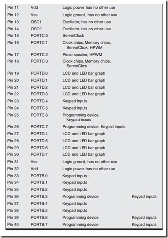
In this particular case, the LAB-X1 board, the MCU is already connected to the items on the board. Therefore, if you want to use the LAB-X1 for your own hard- ware experiments you must use the MCU pins in a way compatible with the com- ponents that are already connected to them. Often, even though the pin is being used in the LAB-X1 circuitry, you can drive something else with it without adversely affecting your experiment (depending on the load being added). Refer to Table 3.1 to quickly determine if the pin and port you want to use is free or how it is being used.

RUNNING SMALL MOTORS-0004

RUNNING SMALL MOTORS-0005RUNNING SMALL MOTORS-0006RUNNING SMALL MOTORS-0007