Light Projects:Interrupt Driven Event Counter with 4-digit LED Display

PROJECT 11 – Interrupt Driven Event Counter with 4-digit LED Display

Function

This project shows how the external interrupt input of the microcontroller can be programmed using the C language. The project is a simple interrupt-based event counter which can count external events from 0 to 9999. A TSM5034 type 4-digit display is connected to port 1 of the microcontroller. Bit 0 of port 3 is connected to a push-button switch S1 which is used to clear the display whenever required. External interrupt input INT0 (pin 6) of the

Light Projects 0094

Light Projects 0095

Light Projects 0096

microcontroller is used as an edge-triggered event input. An external event occurs when INT0 is clocked from 1 to 0.

Circuit Diagram

Figure 3.28 shows a block diagram of the hardware. The push-button switch is the reset input. External events are falling edge triggered. A TSM5034 display shows the event count at any time.

The complete circuit diagram of this project is shown in Fig. 3.29. TSM5034 is connected to port 1 of the microcontroller. The clock input is connected to bit 6 of port 1 and the data input is connected to bit 7 of port 1. Bit 0 of port 3 is connected to the event reset switch S1. This input is normally held at logic 1 with the pull-up resistor R3. When the switch is pressed the pin goes to logic 0 which can be detected by the software. External interrupt input INT0 is used as the event counter input. This pin is normally held at logic 1 with the pull-up resistor R4. An external event occurs when this pin is clocked to 0. This

Light Projects 0097

generates an interrupt in the software which increments the count and displays the total number of events occurred.

Program Description

The program first initializes the interrupt registers of the microcontroller so that external interrupts on pin INT0 can be detected. An endless loop is then

formed with a for statement. Inside this loop the reset input (bit 0 of port 3) is checked and when the reset switch is pressed, the counter is cleared to zero. The interrupt service routine simply increments the current event count and displays the result.

The following PDL describes the functions of the program:

Light Projects 0098

The display part of the program is the same as in Project 10 and is not described here again.

Program Listing

The full program listing is shown in Fig. 3.30. Variable DISPLAY_CLOCK is the clock input of the display and is assigned to bit 6 of port 1. DISPLAY_DATA is the data input of the display and is assigned to bit 7 of port 1. Bit 0 of port 3 is assigned to variable RESET_COUNTER. Variable EVENT is used as the event counter. The program first of all clears the display. The interrupt registers of the microcontroller are then programmed. Statement ITO = I sets external interrupt input INT0 sothat interrupts can be recognized on the falling edge (1 to 0) of this pin. Statement EXO = I enables external interrupt INT0. Statement EA = I enables interrupts sothat they can be accepted by the microcontroller. Inside the endless loop the RESET input is checked. If the user presses RESET (i.e. RESET_COUNTER = O), the counter value EVENT is reset tozero and the display is cleared.

Light Projects 0099

Light Projects 0100Light Projects 0101

The interrupt service routine is declared by the function cnt() interrupt O, where 0 is the interrupt number. 89C2051 interrupt numbers are defined as shown in Table 3.7.

Whenever input INT0 goes from logic 1 to 0 an external interrupt is generated and the program jumps to interrupt service routine declared by function cnt() interrupt O. This routine increments the event counter and displays the result on the TSM5034. The displayed value is thus equal to the total number of events on pin INT0.

Components Required

In addition to the standard components used by the microcontroller, the following components will be required:

Light Projects 0102


Light Projects:Four-digit LED Display Interface

PROJECT 10 – Four-digit LED Display Interface

Function

This project shows how a 4-digit display can be interfaced to a microcontroller. The display we shall be using in this project is the TSM5X34 series 0.311 4-digit

Light Projects 0082

display with on-board driver. This display can be used in many microcon- troller-based applications, including digital clocks, thermometer circuits, instrument readouts, counters, voltmeters and so on. In this project we shall design a 4-digit up-counter which counts from 0 to 9999. We shall be using this display in some of our other projects as a visual readout device.

TSM5X34 Series Displays

The TSM5X34 is a 0.311 4-digit display with on-board serial data input (Fig. 3.22). Serial data transfer from a microcontroller to the display is accomplished with three signals: serial data, data enable, and clock. The data format consists of a leading ‘1’, followed by 35 data bits, each bit corresponding to the segments to be turned on in the display. All of the four digits are programmed at the same time by sending 35 bits of serial data to the display. The clock input is pulsed after each data is sent. The enable input should be at logic 0 to enable programming of the device.

There are mainly two versions of the TSM series of displays. TSM5xxx devices can drive twoexternal LEDs and TSM6xxx series devices incorporate the

Light Projects 0083

colon character as part of the display. In the TSM5xxx series, TSM5034 emits red light, TSM5234 emits green light, and TSM5734 emits high efficiency red light. In this project we shall be using the popular TSM5034 type display.

Thirty-five bits of data should be sent to the display following a ‘1’ start bit. Table 3.5 shows the bit patterns for each segment of the display.

As an example, suppose that we want to turn on segment B of digit 1, segment B of digit 2, segments C and D of digit 3, and segments A, B, and C of digit 4, and we are not connecting any external LEDs to the display, and the decimal points should be off. The bit pattern shown in Fig. 3.23 should then be sent to the display (each bit should be clocked by sending a clock pulse).

Light Projects 0084

The easiest way of controlling the TSM display is to create a table of bit patterns for each decimal digit 0 to 9. If we assume that segment A is the most significant bit in this table, for a given digit we can read the required bit pattern from the table and then send bits to the display by shifting the bits left, one bit at a time for each digit. The total number of data bits sent will be 8 x 4 = 32 bits for 4 digits, 2 bits for the two LEDs, making a total of 34. In addition, we have to send a start bit, making an overall total of 35 bits.

Table 3.6 shows the relationship between the decimal numbers 0 to 9, the corresponding TSM5034 bit patterns, and the corresponding values in hex- adecimal.

As an example, if we want todisplay the decimal number 2367, we have tosend the following bit pattern:

Light Projects 0085

It will therefore be necessary to convert a given number into four decimal digits and then use the above technique to display it.

A required digit can be totally blanked by sending all zeros for that digit. This could be useful when it is required to blank the leading digits instead of displaying zeros if the number to be displayed is less than four digits.

Circuit Diagram

The circuit diagram of Project 10 is shown in Fig. 3.24. The circuit is very simple. Bit 6 of port 1 is connected to the clock input of the display. Similarly, bit 7 of port 1 is connected to the data input of the display. Display pin 7 is the brightness control input and it should be connected to the supply voltage via a suitable resistor. A 0.01 )lF capacitor is recom- mended by the manufacturer as it stops any oscillations. VDD and VLED should normally be connected to + 5 V, although VLED can also be connected to a smaller voltage for lower power consumption. The enable input (pin 3) is connected to the ground. In multiple display operations it is necessary to control the enable input of each device individually so that data and clock can be routed to the required display.

Program Description

The program is a simple 4-digit decimal counter. A counter is initialized to 0 and the display is cleared at the beginning of the program. The counter is then displayed and incremented in an endless loop. The following PDL describes the functions of the program:

Light Projects 0086

Light Projects 0087

Send a clock pulse to the display Shift bit map left by 1 bit

Program Listing

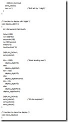
The full program listing is shown in Fig. 3.25. Variable LED is initialized to0 at the beginning of the main program. Function c/ear_disp/ay is then called to clear all digits of the display. The endless loop starts with the for statement. Inside this loop, function disp/ay_a// is called todisplay the value of variable LED as four digits. digits on the TSM5034. The value of variable LED is then incremented and the loop is repeated forever.

Function disp/ay_a// receives the number tobe displayed as its argument (n in this case). This number can range from 0 to 9999. First of all this number is converted into four decimal digits and these digits are stored in integer variables first, second, third, and fourth, where first is digit 1 and fourth is digit 4. Function disp/ay_digit is then called todisplay the digit values. This function stores the bit map of the display in array LED_ARRAY. The bit map corresponding to the number to be displayed is obtained by the statement n = LED_ARRAY[xj. The top bit of this bit map is then examined. If the top bit is a 1 then a 1 is sent to the data input of the display, otherwise a 0 is sent to the data input of the display. The display is then clocked by calling the function send_c/ock, which sends a single clock pulse to the display. The bit map data is then shifted left using the shift operator ‘«’ sothat the second bit can be tested and sent to the display. This is repeated for all 8 bits of the bit map.

Blanking Leading Zeros

The program listing given in Fig. 3.25 displays the data as a 4-digit number with leading zeros. For example, number 27 is displayed as 0027. There are many applications where we may want to blank the leading zeros. It is possible to blank the leading zeros by setting all segments of the leading zero digits to the off state. This is done in the program listing shown in Fig. 3.26. Here, a new bit map 0 is introduced into array LED_ARRAY and the array dimension is increased to11. The new bit map is indexed with number 10. Function disp/ay_a// is changed so that blanks are displayed instead of leading zeros when the number of digits is less than 4. For example, if the number to be displayed is less than 1000, the first digit is displayed by using the bit map defined by LED_ARRAY[IOj, which is 0, i.e. all the segments of the digit are set to0. Similarly, if the number to be displayed is less than 100, the second (and first) digit is displayed with the segments turned off.

General Display Program

There may be some applications where we may need to show leading zeros and also the decimal points. The program listing given in Fig. 3.27 enables both the leading zeros and the decimal points to be optionally displayed. Function

Light Projects 0088

disp/ay_a// displays an integer number between 0 and 9999. This function is called with the following arguments:

display_all(n,lz,dp1,dp2,dp3,dp4) where:

Light Projects 0089Light Projects 0090Light Projects 0091Light Projects 0092Light Projects 0093


Light Projects:7 Segment Display Driver

PROJECT 9 – 7 Segment Display Driver

Function

This project shows how a 7 segment display can be interfaced to a micro- controller. In this project, a 7 segment display is connected to port 1 of the microcontroller and a program is written to count up from 0 to 9 and display the data on the 7 segment display. The program runs in an endless loop and a 1 second delay is used between each output.

Circuit Diagram

Seven segment displays are used in many industrial and commercial applica- tions. Basically the display consists of seven segments of LEDs, connected either as common anode or common cathode. In a common-anode display the anodes of all the LED segments are connected together. Similarly, all the cathodes are connected together in a common-cathode display. Segments in a 7 segment display are identified by giving them letters from a to g as shown in Fig. 3.19.

Light Projects 0075

Light Projects 0076

Light Projects 0077

Required characters are generated by turning on the appropriate LED segments. Table 3.3 shows the segments that should be turned on to generate the decimal numbers 0 to 9. A 1 in the table corresponds to the segment being on.

The circuit diagram of Project 9 is shown in Fig. 3.20. A common-anode type display is used in this project. The anode pins (3 and 8) are connected to +5 V.

Light Projects 0078

Segments a to g are connected to port 1 of the microcontroller via 470 0 current limiting resistors. Segment a is connected to bit 0 of port 1, segment b to bit 1 of port 1, segment c to bit 2 of port 1 and so on.

Program Description

A bit map table has been created which shows the segments to be turned on and the corresponding hexadecimal numbers that should be sent to the display in order to display the required numbers, as shown in Table 3.4 (in this table x is not used but included in the table so that the hexadecimal numbers can be derived easily as two4-bit nibbles).

The following PDL describes the functions of the program:

Light Projects 0079

Light Projects 0080

Program Listing

The full program listing is shown in Fig. 3.21. Variable LED is initialized to0. The 7 segment bit pattern is loaded into array LED_ARRAY. The endless loop is started with the for statement. Data is sent tothe display by indexing the LED_ARRAY with the number tobe displayed. The data is complemented before it is output since the output ports are sourcing current and a segment is turned on when the corresponding output bit is at logic 0. After a 1 second delay, the variable LED is incremented by one, ready for the next display. When variable LED reaches 10 it is reset back to0.

The following data is displayed by the 7 segment display: 0 1 2 3 4 5 6 7 8 9 0 1 2 …

Components Required

In addition to the components used for the basic microcontroller circuit, the following components will be required:

Light Projects 0081


Light Projects:TIL311 Dice

PROJECT 8 – TIL311 Dice

Function

This project is a dice made up from a TIL311 type hexadecimal display. When a push-button switch, connected to bit 0 of port 3, is depressed, a random number between 1 and 6 is displayed on the display. After about 2 seconds the display is cleared and the user can throw a dice again. The program runs in an endless loop.

Circuit Diagram

The circuit diagram of this project is shown in Fig. 3.17. A TIL311 display is connected as in Project 6. Additionally, a push-button switch (S1) is connected to bit 0 of port 3. This pin is normally held at logic 1 with the pull-up resistor R2 and goes to logic 0 when the switch is pressed.

Program Description

The display latch is initially set tologic 1 toavoid any accidental data display. The state of push-button S1 is then checked continuously and when

Light Projects 0072

Light Projects 0073

the button is not pressed, a count is incremented between 1 and 6. When the push-button is pressed, the current value of the count is sent to the display by calling the function out_ti/3II. The above process continues after about 2 seconds delay.

The following PDL describes the functions of the program:

Light Projects 0074

Program Listing

The full program listing is shown in Fig. 3.18 (see pp. 58 and 59). Display latch (variable /atch) is assigned to bit 7 of port 1 using the instruction sbit. Similarly, the push-button is assigned to bit 0 of port 3 and is named button. Variable DICE stores the random dice values.

The display latch is set to1 toavoid any unwanted write to the display and the endless loop starts with the for statement. When the button is pressed (button = 0), the current value of DICE is sent tofunction out_ti/3II which displays the value. After 2 seconds delay the display is cleared and the program loop continues from the beginning.

If the button is not pressed (button = 1), the value of DICE is incremented until it is 7 and then set back to1.

Components Required

In addition to the components used for the basic microcontroller circuit, the following components will be required:

Display TIL311 type hexadecimal display R2 100K, 0.125 W resistor


Light Projects:Two-Digit Decimal Count

PROJECT 7 – Two-Digit Decimal Count

Function

This project shows how a microcontroller can be interfaced to two TIL311 type hexadecimal displays. This project counts up continuously from 0 to 99 in decimal with about a second delay between each count.

Circuit Diagram

The circuit diagram of this project is shown in Fig. 3.15. Two TIL311 type hexadecimal displays are used. Display MSD (most significant digit) will be programmed to show the tens and LSD (least significant digit) will show the units. Data inputs (A, B, C, D) of both displays are connected in parallel to the lower part of port 1 (P1.0 to P1.3). LATCH inputs (pin 5) of the displays are controlled separately. LATCH input of display MSD is connected to P1.7 and the same input of display LSD is connected to P1.6 of the microcon- troller.

MSD data is displayed by sending the data to port 1 and then clocking pin P1.7. Similarly, LSD data is displayed by sending data toport 1 but this time clocking pin P1.6.

Light Projects 0070

Program Description

The count is initially set to 0. The count is then sent to the display using a function called out2_til311. This function separates the variable into two decimal parts (MSD and LSD) and sends each part tothe appropriate display. The next data value is obtained by incrementing the count. When the count reaches 100, it is reset back to 0. The following PDL describes the functions of the program.

Light Projects 0071

Program Listing

The full program listing is shown in Fig. 3.16. LATCH input of display MSD is named /atch_msd and is assigned toport pin P1.7 using the sbit instruction. Similarly, LATCH input of display LSD is named /atch_/sd and is assigned to port pin P1.6. The count (CNT) is initially set to0 and both latches are set to1 to avoid any accidental write to the displays. An endless loop is then formed using the for statement with noarguments. Function out2_ti/3II is called inside the loop to display the value of CNT. CNT is then incremented by 1 and when

it reaches 100, it is reset back to 0. The loop is repeated after a 1 second delay between each output value. The displayed data is:

0 1 2 3 4 5 6 7 8 9 10 … 98 99 0 1 2 …

Function out2_ti/3II receives the data tobe displayed (x) as its argument. This data is then divided by 10 and assigned tointeger variable msd and is the data for the MSD display. The LSD data is calculated by subtracting IO*msd from input variable x and then assigning this toan integer variable named /sd. The top 2 bits of msd data are set to1 by logical ORing the msd data with hexadecimal constant 0xC0. This freezes both displays and avoids any unwanted changes in the displayed data. The value of msd is then sent to port 1 of the microcontroller by clocking the /atch_msd. Similarly, the top 2 bits of the /sd data are set to 1 toavoid any accidental write tothe wrong display and then /sd is sent to port 1 of the microcontroller by clocking the

/atch_/sd bit.

Components Required

In addition to the components used for the basic microcontroller circuit, two TIL311 type hexadecimal displays will be required for this project.


Light Projects:Hexadecimal Display

PROJECT 6 – Hexadecimal Display

Function

This project shows how a microcontroller can be interfaced to a TIL311 type hexadecimal display. The program counts up from 0 to 9 and then in hexadecimal format from A to F and then back to 0. This process is repeated forever with a 1 second delay inserted between each count.

Circuit Diagram

The circuit diagram of this project is shown in Fig. 3.13. TIL311 is a popular 14-pin DIL small hexadecimal display, powered from +5 V. Inputs A, B, C, D of the display are the data inputs and these are connected to the lower part of port 1 (P1.0 to P1.3). LATCH input (pin 5) controls the display. When LATCH is LOW, new data is written tothe display. When LATCH is high, the display data is frozen. The LATCH input of the display is connected to bit 7 of port 1 (P1.7). A new data is displayed by sending the data to the

Light Projects 0066

inputs and then the LATCH input is set tologic LOW and then back toHIGH. Pins 1 and 14 of the display are connected to +5 V and pins 7 and 8 are connected to the ground.

Program Description

The program is very simple. The count is initially set to 0 and the display latch is set to1 toavoid any unintentional write tothe display. The count is then sent to the display and the display latch is clocked. The next data value is obtained by incrementing the count. When the count reaches 16, it is reset back to 0. The following PDL describes the functions of the program. Function out_ti/3II displays data on the TIL311:

Light Projects 0067

Program Listing

The full program listing is shown in Fig. 3.14. Variable /atch is assigned tobit 7 of port 1 using the sbit instruction of the compiler. Variable CNT is initialized to0 and function out_ti/3II is called todisplay the value of CNT. CNT is then incremented by 1. When CNT is 16, it is reset back to0. The loop is repeated forever after a 1 second delay between each count. The displayed data is:

0 1 2 3 4 5 6 7 8 9 10 A B C D E F 0 1 …

Function out_ti/3II receives the data tobe displayed as its argument (i.e. x). The /atch is initially set to1 by logical ORing the data with hexadecimal value 0x80. The /atch is then set to0 toenable the data tobe written tothe display and then back to1 tofreeze the display.

Light Projects 0068

It is interesting to note that, in many programming applications a variable is incremented and then tested tosee whether it reached a constant value. An example is given in Fig. 3.14 where variable CNT is used:

Light Projects 0069

Components Required

In addition to the components used for the basic microcontroller circuit, a TIL311 type hexadecimal display will be required for this project.


Light Projects:LED Dice

PR0JECT 5 – LED Dice

Function

This project simulates a dice by displaying a random number between 1 and 6, on six LEDs connected to port 1 of the microcontroller. Bit 0 of port 3 (P3.0) is used as the input and a push-button switch is connected to this pin. Every time the switch is pressed, a new number is displayed.

Circuit Diagram

The circuit diagram of this project is shown in Fig. 3.9. Bit 0 of port 3 is normally held at logic HIGH with the pull-up resistor R3. When switch S1 is pressed, bit 0 of port 3 moves to logic LOW and is detected by the software. As

Light Projects 0057

shown in Fig. 3.9, the seven LEDs have been mounted in a pattern to emulate the dots on a real dice. The pattern displayed for different numbers is shown in Fig. 3.10. As in a real dice, the first row can have up to two LEDs on (corresponding to two dots on a dice), the second row up to three LEDs on, and the third row can have up to two LEDs on.

Light Projects 0058

Program Description

A random dice number is obtained during scanning of the push-button switch as follows. The program scans the push-button switch continuously. If the switch is not pressed (i.e. at logic HIGH), a number is incremented between 1 and 6. Whenever the push-button is pressed, the current value of the number is read and this value is used as the new dice number. Since the switch is pressed by the user in random, the numbers generated are also random numbers from 1 to 6. The new random number is displayed on the seven LEDs appropriately.

After about 2 seconds delay, all LEDs are turned off and the above process is repeated forever. The following PDL describes the functions of the program:

Light Projects 0059

Table 3.1 shows the random numbers generated and the corresponding LEDs that will be turned on to give the dice display of Fig. 3.10.

As an example, if the number 3 is tobe displayed then only LEDs D3, D4, and D5 will be turned on. Similarly, for number 6, all LEDs except LED 4 will be turned on.

Program Listing

The full program listing is shown in Fig. 3.11. Variable ON is defined as 0 and

Light Projects 0060

Light Projects 0061

Light Projects 0062

variable ALL_OFF is defined as hexadecimal oxFF (i.e. all bits set). These variables will be used to turn an LED on or to turn all LEDs off. Variable button is assigned to bit 0 of port 3 using the C compiler sbit statement. Similarly, the seven LEDs are assigned to bits 0 to 7 of port 1 using the sbit statement.

Variable DICE is declared as an integer and holds the dice values. Inside the endless for loop, variable button is tested. If button is 0, i.e. if the user presses the push-button, then a switch statement is used to turn on the appropriate LEDs as defined in Table 3.1. As an example, if the value of DICE is 2, LEDs D3 and D5 are turned on and the others are turned off. The break instructions ensure that we jump out of the switch statement after executing a case block. A dice value is displayed for 2 seconds and after this time all the LEDs are turned off. If inside the endless for loop the button is not pressed (i.e. button is 1), then variable DICE is incremented continuously. When DICE is 7, it is set back to1.

A More Effcient Program

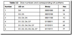
Notice that in this program we have used a switch statement and executed the correct case block depending on the value of variable DICE. We can make the program much more efficient and easy to follow if we create a simple table (an array in the program) and in this table store the dice numbers against the hexadecimal values of LED patterns. Table 3.2 shows the relationship between the dice numbers, the LED patterns and the corresponding binary and hexadecimal equivalents.

As an example, todisplay number 3 pattern, all we have to dois send hexadecimal number 1C toport 1. Similarly, sending 77 will display the dice pattern for number 6 on the LEDs.

The program listing given in Fig. 3.12 uses Table 3.2 to display dice patterns. The hardware setup is again the same and bit 0 of port 3 is used as the push-

Light Projects 0063

This is a dice simulator project. Seven LEDs are connected to port l of the microcontroller and mounted as shown in the text. A push-button switch is connected to bit 0 of port 3 and when this switch is depressed, a new number is obtained between l and 6 and the corresponding LEDs are turned on to simulate a dice. After 2 seconds delay, all LEDs are turned off and the user can throw a dice again.

Light Projects 0064

button input. An integer array DICE_ARRAY is created tostore the hexadecimal bit patterns as described in the table. Index 0 of this array corresponds to dice number 1 (pattern generated by hexadecimal number 8) and index 1 corresponds to dice number 2 (pattern generated by hexadecimal number 14) and so on. Because the arrays in C are indexed from 0, we have to subtract 1 from the array index in order to get the correct value. As shown in the program listing in Fig. 3.12, variable button is tested inside the endless loop. If the push-button is pressed, the hexadecimal bit pattern corresponding to variable DICE-I is obtained using the statement DICE_ARRAY[DICE-Ij and this value is complemented and sent to port 1 of the microcontroller. All the displays are turned off after about 2 seconds delay. If the push-button is not pressed, variable DICE is incremented continuously and set back to 1 when it reaches 7.

Components Required

In addition to the components required by the basic microcontroller circuit, the following components will be required for this project:

Light Projects 0065


Light Projects:Cyclic LED Pattern

PR0JECT 4 – Cyclic LED Pattern

Function

This project turns on the LEDs connected to port 1 in a cyclic manner such that first only 1 LED is on, then 2 LEDs are on, then 3, 4, 5, … , 8 are on (Fig. 3.7). The process is repeated indefinitely with 1 second delay between each output pattern.

Circuit Diagram

The same circuit (Fig. 3.2) as in Project 1 is used. The LEDs can be mounted in different patterns and in different colours depending upon the application.

Program Description

The program is required to turn on the first LED (e.g. corresponding to number 128) and then after a second delay turn on the LEDs corresponding to

Light Projects 0055

numbers 64, 32, 16 and so on until all eight LEDs are on (number 255). The process is then repeated forever as shown in Fig. 3.7 with about 1 second delay between each output pattern. The following PDL describes the functions of the program:

Light Projects 0056

Program Listing

The full program listing is shown in Fig. 3.8. Variable LED is initialized to128 (top bit on) and used to hold the data. This value is complemented and output to port 1, and then shifted right by 1 digit using the C operator ‘»’. When all the LEDs are on (LED = 255), the last value in the chain is displayed and variable LED is set back to 128. The above process is repeated forever with about 1 second delay between each output pattern.


Light Projects:Random LED Pattern

PR0JECT 3 – Random LED Pattern

Function

This project turns on the LEDs connected to port 1 randomly. A random number is generated between 0 and 32 767 using the built-in C function rand and then this is output to turn on the corresponding LEDs. The data is displayed with about 1 second delay between each output pattern.

Light Projects 0053

Circuit Diagram

The same circuit (Fig. 3.2) as in Project 1 is used . The LEDs can be mounted in different patterns and in different colours depending upon the application.

Program Description

The program is required to generate a random number and then output this number to port 1 in order to turn on the corresponding LEDs. A small delay is required between each output so that the LED patterns can be seen. The following PDL describes the functions of the program:

Light Projects 0054

Variable P1 is defined in include file ‘AT892051.h’ and this is a reserved name for port 1 of the microcontroller. The built-in C function rand() generates a random integer number between 1 and 32 767 and this function is used to generate a random number and store it in variable LED. The generated number is complemented and output to port 1 of the microcontroller and the process is repeated indefinitely with about 1 second delay between each output pattern.


Light Projects:LED Chasing Circuit

PR0JECT 2 – LED Chasing Circuit

Function

This project turns on the LEDs connected to port 1 of the microcontroller in sequence, resulting in a chasing LED effect. The data is displayed with about 1 second delay between each output pattern. Figure 3.4 shows the output pattern displayed by the LEDs.

Circuit Diagram

The same circuit (Fig. 3.2) as in Project 1 is used. The LEDs can be mounted in a circular or in some other geometric form to enhance the chasing effect. Also, different coloured LEDs can be used to give a colourful output.

Light Projects 0051

Program Description

The program is required to load a 1 into the top (or bottom) bit of a variable and then shift the data right (or left) by one digit and display on the LEDs. A delay will be required between each output. The following PDL describes the functions of the program. In this PDL, the top bit of a variable is loaded and data is shifted tothe right:

Light Projects 0052

Program Listing

The full program listing is shown in Fig. 3.5. Variable LED is initialized to128 (top bit set to 1) and is used as the counter. The endless loop is set using the for statement with noparameters. Variable P1 is defined in include file ‘AT892051.h’ and this is a reserved name for port 1 of the microcontroller. Notice that variable LED is complemented and then sent to the output port. This is necessary since the output ports are configured to source current, i.e. an LED is turned on when the corresponding port output is logic LOW. The count value is shifted right by one digit using the C compiler operator ‘»’.

When the count reaches 0, it is reloaded with 128, i.e. the values of variable LED will be 128, 64, 32, 16, 8, 4, 2, 1, 128, … A delay of approximately 1 second is obtained by the function wait_a_second.