Temperature Projects:Using a Digital Temperature Sensor

PROJECT 17 – Using a Digital Temperature Sensor

Function

This project shows how we can interface a DSI620 type digital temperature sensor to our microcontroller. The ambient temperature is measured con- tinuously and then displayed in degrees centigrade on three TIL3II type alphanumeric displays. Positive temperature is displayed from 0oC toI25oC. Negative temperature is displayed with a leading letter ‘E’ in the range down to -55oC.

Circuit Diagram

The block diagram of this project is shown in Fig. 5.I. DSI620 is a digital IC temperature sensor which measures the ambient temperature and provides the output as 9 bits of digital serial data. The microcontroller extracts the temperature data from the DSI620 and then displays the temperature on three TIL3II type alphanumeric displays.

Before describing the circuit diagram in detail, it is useful to look at the operation of the DSI620 temperature sensor IC.

Temperature Projects-0024

DS1620 Digital Thermometer IC

DSI620 is a digital thermometer and thermostat IC that provides 9 bits of serial data to indicate the temperature of the device. The pin configuration of the DSI620 is shown in Fig. 5.2. VDD is the power supply which is normally connected to a +5 V supply. DQ is the data input/output pin. CLK is the clock input. RST is the reset input. The device can alsoact as a thermostat. THIGH is driven high if the DSI620’s temperature is greater than or equal to a user defined temperature TH. Similarly, TLOW is driven high if the DSI620’s temperature is less than or equal to a user defined temperature TL. TCOM is driven high when the temperature exceeds TH and stays high until the temperature falls below TL. User defined temperatures TL and TH are stored in non-volatile memory of the device so that they are not lost even after removal of the power.

Data is output from the device as 9 bits, with the LSB sent out first. The temperature is provided in 2’s complement format from -55oC to +I25oC, in steps of 0.5oC. Table 5.I shows the relationship between the temperature and data output by the device.

Temperature Projects-0025

Temperature Projects-0026

Data input and output is through the DQ pin. When RST input is high, serial data can be written or read by pulsing the clock input. Data is written or read from the device in two parts. First, a protocol is sent and then the required data is read or written. The protocol is 8-bit data and the protocol definitions are given in Table 5.2. For example, to write the thermostat value TH, the hexadecimal protocol data 0I is first sent to the device. After issuing this

Temperature Projects-0027

command, the next nine clock cycles clock in the 9-bit temperature limit which will set the threshold for operation of the THIGH output.

For example, the following data (in hexadecimal) should be sent to the device to set it for a TH limit of +50oC and TL limit of +20oC and then subsequently to start the conversion:

Temperature Projects-0028

A configuration/status register is used to program various operating modes of the device. This register is written with protocol 0C (hex) and the status is read with protocol AC (hex). Some of the important configuration/status register bits are as follows:

Temperature Projects-0029

The complete circuit diagram of this project is shown in Fig. 5.3. Bit 2 of port 3 is connected to the RST input of DSI620, bit I is connected to the clock input and bit 0 of port 3 is connected to the DQ pin of the DSI620. Three TL3II type alphanumeric displays are connected to port I of the microcontroller. Digit I is controlled from bit 7 of port I, digit 2 from bit 6 of port I, and digit 3 from bit 5 of port I.

Program Description

The program reads the temperature from the DSI620 thermometer IC and displays the temperature on three TIL3II type displays continuously with I second delay between each displayed output. The following PDL describes the operation of the program:

Temperature Projects-0030

Temperature Projects-0031

Program Listing

The full program listing is given in Fig. 5.4. The display digit latches and the DSI620 control lines are assigned to bit variables at the beginning of the program. Also the used protocols are defined and assigned to global variables. For example, read_temp is assigned tohexadecimal number AA, start_conv is assigned tohexadecimal number EE and so on.

When the program starts, the digit latches digit1_latch, digit2_latch, and digit3_latch are all set to I to avoid any erroneous writes to the displays. A function conigure_ds1620 is then called to set the configuration register/status

Temperature Projects-0032

Temperature Projects-0033

Temperature Projects-0034

Temperature Projects-0035

for continuous operation. Temperature conversion is then started by calling the function start_temp_conversion. This function sends protocol EE (hex) to the DSI620. An endless loop is then formed using the for statement with no parameters. Inside this loop, function read_temperature reads the 9-bit temperature value and returns in variable TEMP. Function display_temperature displays the temperature on the three TIL3II displays. This loop is repeated with about a I second delay between each output.

Function read_temperature returns the temperature tothe calling program as an unsigned integer. This function calls function read_from_ds1620 with the argument AA (in hex) toget the temperature. Function read_from_ds1620 is a general routine which reads data from the DSI620. This function sends a protocol data to the DSI620 and then reads data bytes from the DSI620 corresponding to the sent protocol. The RST input of the device is first set to I. A for loop is then formed to iterate eight times to send serial protocol data to the DSI620. LSB is sent out first. Local variable this_bit stores the bit to be sent out at each iteration. Another for loop reads data from the DSI620 and stores this data in variable ds1620_data. At the end of the read cycle the RST input is set back to0 and the data in ds1620_data is returned tothe caller.

Function write_to_ds1620 is a general function and it sends a protocol, followed by data bits, to the DSI620. The RST input of the DSI620 is first set toI. A for loop is then formed to iterate eight times and the protocol bits are sent out serially to the DQ input of the DSI620. Variable this_bit stores the bit to be sent out at each iteration. After this, another for loop sends out the required number of data bits to the DSI620. At the end of the write cycle, the RST input is returned to0.

Function display_temperature receives the temperature data as its argument and displays the temperature on the three TIL3II type alphanumeric displays. If the temperature is negative, the first display digit is set todisplay letter ‘E’. The temperature value tobe displayed is divided by 2 since the temperature is returned by the DSI620 in 0.5oC intervals. For example, a reading of decimal I00 corresponds to 50oC. Each digit is displayed after converting the data to decimal format.

Components Required

In addition to the basic components required by the microcontroller, the following components will be required for this project:

Temperature Projects-0036


Temperature Projects

Temperature measurement and control is one of the most common applica- tions of microcontroller-based data acquisition systems. Four types of sensors are commonly used to measure temperature in commercial and industrial applications. These are thermocouples, resistive temperature devices (RTDs), thermistors, and integrated circuit (IC) temperature sensors. Each sensor has its unique advantages and disadvantages and by understanding how these sensors work, and what types of signal conditioning are required for each, we can make more accurate and reliable temperature measurement, monitoring, and control.

The typical characteristics of various temperature sensors are:

• Thermocouples: these are inexpensive, and the most common temperature sensors with a wide range of temperature range. Thermocouples work on the principle that when two dissimilar metals are combined, a voltage appears across the junction between the metals. By measuring this voltage, we can get a temperature reading. Different combinations of metals create different thermocouple voltages and there is a wide range of thermocouples available for different applications. Thermocouples generate very low voltages, typically 50 !lV/oC. These low-level signals require special signal conditioning to remove any possible noise. Thermocouples have non-linear relationships to the measured temperature and as a result it is necessary either to linearize the characteristics or to use look-up tables to obtain the actual temperature from the measured voltage.

• RTDs: an RTD is a resistor with its resistance changing with temperature.

The most popular type of RTD is made of platinum and has a resistance of I00 0 at 0oC. Because RTDs are resistive devices, a current must pass through the RTD to produce a voltage that can be measured. The change in resistance is very small (about 0.4 0/oC) and special circuitry is generally needed tomeasure the small changes in temperature. One of the drawbacks of RTDs is their non-linear change in resistance with temperature.

• Thermistors: thermistors are metal oxide semiconductor devices whose resistance changes with temperature. One of the advantages of thermistors is their fast responses and high sensitivity. For example, a typical thermistor

may have a resistance of 50 k0 at 25oC, but have a resistance of only 2 k0 at 85oC. Like RTDs, a current is passed through a thermistor and the voltage across the thermistor is measured. Thermistors are very non-linear devices and look-up tables are usually used to convert the measured voltage to temperature. Thermistors are very small and one disadvantage of this is that they can be self-heating under a large excitation current. This of course increases the temperature of the device and can give erroneous results.

• IC temperature sensors: integrated circuit temperature sensors are usually 3- or 8-pin active devices that require a power supply to operate and give out a voltage which is directly proportional to the temperature. There are basically two types of IC temperature sensor: analogue sensors are usually 3-pin devices and give out an analogue voltage of typically I0 mV/oC which is directly proportional to the temperature; digital temperature sensors provide 8- or 9-bit serial digital output data which is directly proportional tothe temperature.

In this chapter we shall be looking at how we can interface various temperature sensors to our microcontroller in order to measure and display the ambient temperature.


ELECTRONIC CIRCUITS AND DIGITAL:BINARY NUMBERS

BINARY NUMBERS

The binary number system is a set of rules and procedures for representing and processing numerical quantities in digital equipment. Because the base of the binary number system is 2, only two symbols (0 and 1) are used to represent any quantity. The symbols 0 and 1 are called binary digits or bits. For example, the 6-bit number 101101 represents the decimal number 45. Your understanding of how digital circuits, microprocessors, and related equipment process data is tied directly to an understanding of the binary number system.

The reason for using binary numbers in digital equipment is the ease with which they can be implemented. The electronic components and circuits used to represent and process binary data must be capable of assuming two discrete states to represent 0 and 1. Examples of two-state components are switches and transistors. When a switch is closed or on, it can represent a binary 1. When the switch is open or off, it can represent a binary 0. A conducting transistor may represent a 1, whereas a cut-off transistor may represent a 0. The representation may also be voltage levels. For example, a binary 1 may be represented by +3.3 V and a binary 0 by 0 V as previously shown in Figure 5.1.

Binary-to-Decimal Conversions

The binary system is similar to the decimal system in that the position of a digit in a number determines its weight. Recall that in the decimal system the weights are powers of 10. The right-most digit is units or 1’s, and then 10’s, 100’s, 1000’s, and so on, moving from right to left from one digit to the next. The position weights of a binary number are powers of 2:

Electronics-Explained-0085_thumb1_th

Now let’s evaluate the decimal quantity associated with a given binary number, 101101. You simply multiply each bit by its position weight and add the values to get the decimal equivalent, 45.

Electronics-Explained-0086_thumb_thu

You can see that positions with a 0 bit have no effect on the value. Therefore, they can be ignored. To quickly determine the decimal equivalent of a binary number, simply sum the weights of the positions containing a 1 bit. For example, in the number 11101, the weights of those positions with a 1 bit from right to left are 1 + 4 + 8 + 16 = 29.

Using Hardware to Represent Binary Quantities

Switches are widely used to enter binary data into computers and digital equipment. If the switch is set to the up position, a binary 1 is represented. If the switch is down, a binary 0 is represented. The switch contacts can be open or closed depending on the circuit in which the switch is connected. Figure 5.2 shows a group of slide switches set to represent a binary number, 11000101 or 197.

Indicator lights such as light-emitting diodes (LEDs) are sometimes used to read out binary data in digital equipment. An “on” light is a binary 1 and an “off” light is a binary 0. See Figure 5.3. The decimal value being represented by the display is 178.

Decimal-to-Binary Conversions

You may find it necessary to convert decimal numbers into their binary equivalents. This can be done by dividing the decimal number by 2, dividing the quotient by 2, dividing that quotient by 2, and so on, recording the remainders until the quotient is zero. The remainders form the binary equivalent.

Electronics-Explained-0087_thumb_thu

Electronics-Explained-0088_thumb_thu

You can always check your work by reconverting the binary number back to decimal using the procedure described earlier. Also, keep in mind that some scientific calculators can do binary-to-decimal and decimal-to-binary conversions.

Another name for a binary number is binary word. The term word is more general. It refers to a fixed group of bits that can mean numbers, letters, or special characters and codes. We say that digital equipment processes binary data words.

All digital circuits and microcomputers work with a fixed-length binary word. A common binary word length in microcomputers and other digital equipment is 8 bits. All data storage, processing, manipulation, and trans- mission are carried out in 8-bit groups. Word lengths of 4, 8, 12, 16, 32, and 64 bits are common in digital equipment.

An 8-bit word is usually called a byte. In data communication applications, an 8-bit word is sometimes called an octet. A 4-bit word is sometimes referred to as a nibble.

Maximum Decimal Value for N Bits

The number of bits in a binary word determines the maximum decimal value that can be represented by that word. This maximum value is determined with the formula:

Electronics-Explained-0089_thumb_thu

where M is the maximum decimal value and N is the number of bits in the word.

For example, what is the largest decimal number that can be represented by 4 bits?

Electronics-Explained-0090_thumb_thu

With 4 bits, the maximum possible number is binary 1111, or decimal 15.

The maximum decimal number that can be represented with 1 byte is 255 or 11111111. An 8-bit word greatly restricts the range of numbers that can be accommodated. But this is usually overcome by using larger words.

There is one important point to know before you leave this subject. The formula M = 2N – 1 determines the maximum decimal quantity (M) that can be represented with a binary word of N bits. This value is 1 less than the maxi- mum number of values that can be represented. The maximum number of values that can be represented (Q) is determined with the formula:

Electronics-Explained-0091_thumb_thu

With 8 bits, the maximum number of values is 256 or 0 through 255.

Table 5.1 gives the number of bits in a binary number and the maximum number of states that can be represented.

Electronics-Explained-0092_thumb_thu

The binary numbers we have been discussing are usually referred to as pure binary codes. But there are other types of binary codes. For example, the binary-coded decimal (BCD) system is popular. BCD is a hybrid code between the binary and decimal systems. It was developed in an attempt to simplify the conversion processes between the two systems and to improve human–machine communication.

To represent a decimal number in the BCD system, each digit is replaced by its 4-bit binary equivalent. Thus, the number 729 in BCD is:

Electronics-Explained-0093_thumb_thu

The BCD code is given in Table 5.2.

It is important to note that the 4-bit binary numbers 1010 through 1111 that represent the decimal values 10 through 15 are invalid in BCD.

To convert a BCD number to decimal, simply substitute the decimal equivalent of each 4-bit group. The BCD number 1001 0100 0110 in decimal is 946.

A special form of BCD code is used in computers and data communications systems. It is a 7- or 8-bit code that is used to represent not only numbers but also letters (both uppercase and lowercase), special symbols, and control functions. This code is called the American Standard Code for Information Interchange, or ASCII (pronounced “ask-key”).

Electronics-Explained-0094_thumb_thu

The complete ASCII is given in Table 5.3. It provides the decimal and hexadecimal (hex) values of the codes. The code contains both uppercase and

Electronics-Explained-0095_thumb_thu

Electronics-Explained-0096_thumb_thulowercase letters, the digits 0 through 9, punctuation marks, common mathematical symbols, and many special two- and three-letter codes. The special codes are known as control codes. They are used to indicate the start and end of a string of characters or to initiate special operations. Some examples follow:

Electronics-Explained-0097_thumb_thu

Electronics-Explained-0098_thumb_thu

Parallel and Serial Data

It is frequently necessary for digital devices to communicate. Someone using a computer may have to send data to a printer. Or two people using personal com- puters may have to communicate over a local area network (LAN). To accomplish either of these objectives, one must transmit binary data from one circuit to another. This is done in one of two ways: parallel transmission or serial transmission.

Parallel Data

When the parallel method is used, all bits of a binary word or number are transmitted simultaneously. Figure 5.4 shows an 8-bit word being transferred from logic circuit 1 to logic circuit 2.

A bus is a set of parallel data lines over which digital data is transferred. A data bus can have any number of data lines as required by the application. However, the main characteristic of a bus is parallel data transfer. In physical form, a bus is usually implemented on a connector, with lines of copper on a printed circuit board or with a ribbon cable with one wire per bit.

Because all bits are transmitted at the same time over a parallel bus, data movement is extremely fast. The main benefit of parallel data transmission is its high speed. With high-speed logic circuits, a binary word can be transferred from one point to another in as little as several nanoseconds. Parallel data trans- mission over buses in computers takes place at rates up to several hundred meg- ahertz. It is not uncommon to see a rate of 100 million bits per second (Mbps)

Electronics-Explained-0099_thumb_thu

on a personal computer data bus. On long buses, data rates are slower because the stray inductance and capacitance of the cable typically distorts the data and slows the transmission speed.

Although parallel transmission is fast, it is expensive, because there must be circuitry for each bit on both the sending and receiving ends. There must be one wire per bit in a cable plus a separate ground wire. This increases the complexity and thereby the cost of the circuitry.

Serial Data

The other method of moving binary data from one point to another is serial transmission. In the serial method, the bits of a word are transmitted one at a time, or sequentially. Figure 5.5 shows the waveform of an 8-bit serial binary word. This is the voltage that you would monitor at the single output of the circuit generating the word. It is the waveform that an oscilloscope would dis- play. Each bit occurs for a fixed time interval such as 1.5 milliseconds. Thus, it takes 1.5 X 8 = 12 milliseconds (ms) to transmit an 8-bit word.

The speed of data transmission is measured in bits per second (bps). That figure can be calculated from the expression:

Electronics-Explained-0100_thumb_thu

As seen in Figure 5.5, the MSB is transmitted first. Depending on the system used, however, the LSB can be sent first. In any case, the speed of transmission depends on the number of bits in the word and the duration of each bit. It is this longer transmission time that is the primary disadvantage of the serial method. However, although serial transmission is slower than parallel transmission, it is perfectly suitable for many applications. Common data rates are in excess of millions of bits per second. Data rates of more than 10 Gbps are common.

The main benefits of the serial method are its simplicity and low cost. Only a single line rather than multiple lines is needed to interconnect the equipment. In addition, only one set of sending and receiving circuits is needed. All data transmissions by copper cable or fiber optical cable exceeding about 100 Mbps are made by the serial method. All wireless data transmissions are serial.


AUDIO ELECTRONICS:CABLE TELEVISION

CABLE TELEVISION

It is estimated that about 15% of all U.S. citizens get their TV over the air with an antenna. But over 70% get TV via cable. The remaining 15% get satellite TV. Why? Mainly because cable offers not only better, more reliable signals than by antenna, but also offers hundreds of channels of programming. But that’s not all. Most of those who have cable also use the cable connection for

Electronics-Explained-0226_thumb_thu

high-speed Internet access service. Of course, you pay for all that, and it has become like a monthly utility bill. With the cable industry being so big, it pays to know a little more about it.

It all starts with a facility called the cable head end. Another name you might hear is cable modem termination system (CMTS), which specifically is the equipment at the head end. This is a place where the company collects video and programming from many different sources. It snatches signals off the air, it receives premium programming like HBO, ESPN, Showtime, and Fox via satellites, stores movies on its large computers called video servers, and may even do some of its own local programming. The result is a hundred channels or more.

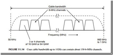
Now each of those TV signals—video plus audio—is modulated onto carriers that are spaced 6 MHz apart just like the regular over-the-air TV channels. Then all of those modulated carriers are added together to form a very complex signal. That signal is then amplified and put on the outgoing cable. Figure 11.14 shows what the spectrum looks like. Most cables have a bandwidth from about 50 MHz up to about 860 MHz to 1 GHz, which will accommodate up to about 130 6-MHz channels. We call this process frequency-division multiplexing, where a single cable can carry many separate channels of data, each on a different frequency and bandwidth. And since the cable is shielded, it does not radiate, so it, in effect, duplicates the free-space electromagnetic spectrum.

Since most TV today is digital, digital modulation methods are used to put multiple TV signals within each 6-MHz channel. Using 16-QAM or 64-QAM, a cable company can squeeze several channels of video/audio into each 6-MHz chunk of spectrum, providing hundreds of additional slots for programming. That is why cable companies can advertise up to 500 channels of entertainment, news, and so on.

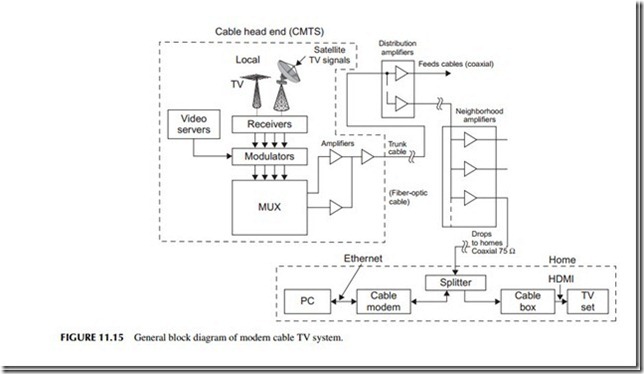
All of the digital video/audio signals are then remodulated onto different channel assignments. All of these 6-MHz channels are added together or linearly mixed in a multiplexer (MUX) to create a massively complex compos- ite signal. This is what goes out on the cable (see Figure 11.15).

Electronics-Explained-0227_thumb_thu

The signal distribution network is called a hybrid fiber cable (HFC) system. This multiplexed signal is applied to a fiber optic cable, called a trunk cable. It is routed around the city and it terminates at selected points where the signal is divided into multiple paths of coax cable. These so-called feeder cables are connected to amplifiers along the way to overcome the large attenuation of the cables. At some point, the feeder cables come into your neighborhood and are further amplified and split into multiple signals. These signals are then sent to your house by a coax drop cable. The most common type is 75-ohm RG-6/U coax with F-connectors. The cable comes into your home and is usually split two or more times and sent to wall connectors in the various rooms. These connectors connect the signal to a cable box and/or a cable modem for the PC. The cable box is like a tuner in that its main job is to select one of the many channels and send it to your TV set. Figure 11.16 shows a simplified block diagram of a typical cable box, usually called a set-top box (STB). The input is a TV tuner with channel selection via a frequency-synthesizer local oscillator by way of your remote control. The selected signal is then demodulated and decompressed by a digital media processor chip, and then sent to the TV set via one of the many possible interfaces, usually the HDMI or high-definition multi- media interface. This is a very fast digital interface with special cable and con- nector. Most TV sets have this as the most common input. Other video format interfaces such as RGB, PrPbPy, or S-video, are usually provided to accommo- date older analog TV sets. An additional feature of many of the newer STBs is a built-in digital video recorder (DVR). This is essentially a computer hard disc

Electronics-Explained-0228_thumb_thu

drive that records the program you want to save for viewing later.

Electronics-Explained-0229_thumb_thuFor Internet access, you connect a cable modem to the coax cable and it automatically selects the channel where the data services are assigned. The modem goes to your computer via an Ethernet cable. Access to the Internet is by way of your computer’s browser.


AUDIO ELECTRONICS:CABLE TELEVISION

CABLE TELEVISION

It is estimated that about 15% of all U.S. citizens get their TV over the air with an antenna. But over 70% get TV via cable. The remaining 15% get satellite TV. Why? Mainly because cable offers not only better, more reliable signals than by antenna, but also offers hundreds of channels of programming. But that’s not all. Most of those who have cable also use the cable connection for

Electronics-Explained-0226_thumb

high-speed Internet access service. Of course, you pay for all that, and it has become like a monthly utility bill. With the cable industry being so big, it pays to know a little more about it.

It all starts with a facility called the cable head end. Another name you might hear is cable modem termination system (CMTS), which specifically is the equipment at the head end. This is a place where the company collects video and programming from many different sources. It snatches signals off the air, it receives premium programming like HBO, ESPN, Showtime, and Fox via satellites, stores movies on its large computers called video servers, and may even do some of its own local programming. The result is a hundred channels or more.

Now each of those TV signals—video plus audio—is modulated onto carriers that are spaced 6 MHz apart just like the regular over-the-air TV channels. Then all of those modulated carriers are added together to form a very complex signal. That signal is then amplified and put on the outgoing cable. Figure 11.14 shows what the spectrum looks like. Most cables have a bandwidth from about 50 MHz up to about 860 MHz to 1 GHz, which will accommodate up to about 130 6-MHz channels. We call this process frequency-division multiplexing, where a single cable can carry many separate channels of data, each on a different frequency and bandwidth. And since the cable is shielded, it does not radiate, so it, in effect, duplicates the free-space electromagnetic spectrum.

Since most TV today is digital, digital modulation methods are used to put multiple TV signals within each 6-MHz channel. Using 16-QAM or 64-QAM, a cable company can squeeze several channels of video/audio into each 6-MHz chunk of spectrum, providing hundreds of additional slots for programming. That is why cable companies can advertise up to 500 channels of entertainment, news, and so on.

All of the digital video/audio signals are then remodulated onto different channel assignments. All of these 6-MHz channels are added together or linearly mixed in a multiplexer (MUX) to create a massively complex compos- ite signal. This is what goes out on the cable (see Figure 11.15).

Electronics-Explained-0227_thumb

The signal distribution network is called a hybrid fiber cable (HFC) system. This multiplexed signal is applied to a fiber optic cable, called a trunk cable. It is routed around the city and it terminates at selected points where the signal is divided into multiple paths of coax cable. These so-called feeder cables are connected to amplifiers along the way to overcome the large attenuation of the cables. At some point, the feeder cables come into your neighborhood and are further amplified and split into multiple signals. These signals are then sent to your house by a coax drop cable. The most common type is 75-ohm RG-6/U coax with F-connectors. The cable comes into your home and is usually split two or more times and sent to wall connectors in the various rooms. These connectors connect the signal to a cable box and/or a cable modem for the PC. The cable box is like a tuner in that its main job is to select one of the many channels and send it to your TV set. Figure 11.16 shows a simplified block diagram of a typical cable box, usually called a set-top box (STB). The input is a TV tuner with channel selection via a frequency-synthesizer local oscillator by way of your remote control. The selected signal is then demodulated and decompressed by a digital media processor chip, and then sent to the TV set via one of the many possible interfaces, usually the HDMI or high-definition multi- media interface. This is a very fast digital interface with special cable and con- nector. Most TV sets have this as the most common input. Other video format interfaces such as RGB, PrPbPy, or S-video, are usually provided to accommo- date older analog TV sets. An additional feature of many of the newer STBs is a built-in digital video recorder (DVR). This is essentially a computer hard disc

Electronics-Explained-0228_thumb

drive that records the program you want to save for viewing later.

Electronics-Explained-0229_thumbFor Internet access, you connect a cable modem to the coax cable and it automatically selects the channel where the data services are assigned. The modem goes to your computer via an Ethernet cable. Access to the Internet is by way of your computer’s browser.


Sound Projects:Electronic Organ (Using the Timer Interrupt)

PROJECT 16 – Electronic Organ (Using the Timer Interrupt)

Function

This is a simple electronic organ project. A small speaker is connected to bit 0 of port 3 via a MOSFET transistor. Eight push-button switches are connected to port I to act as the keyboard for the electronic organ. Timer I of the microcontroller is used to generate time delays for the required frequencies. Only one octave (eight notes) is provided.

Circuit Diagram

The circuit diagram of this project is shown in Fig. 4.8. The speaker is connected to bit 0 of port 3. The keyboard switches are connected to port I.

Sound Projects-0018

Bit 0 is assigned tonote C, bit I is assigned tonote D, bit 2 is assigned tonote E and so on. The switches are normally held at logic HIGH with pull-up resistors (R2 to R9). Pressing a switch sends a logic LOW to the microcontroller port.

Program Description

In this project timer I is used to generate the tones for the electronic organ. The timer is in auto-reload mode and loaded to generate an interrupt every 50 !ls (i.e. loaded with 206 for a I2 MHz crystal). An endless for loop is formed and the keyboard is scanned. When a key is pressed, the timer is reloaded with the correct value so that the required tone can be generated.

The following octave was used for this project (the frequencies are in Hz):

Sound Projects-0019

The periods of the notes in !ls are then given by (period = I/frequency):

Sound Projects-0020

Program Listing

The full program listing is shown in Fig. 4.9. When the program is started, the speaker is turned off and timer I is initialized to 8-bit auto-reload mode by calling function init_timer. An endless for loop is then formed and the keyboard is scanned. Normally port I contains the value 0xFF (255) when no keys are pressed. When a key is pressed the pin corresponding to that key goes to logic LOW. Variable key_pressed reads port I and complements the

Sound Projects-0021

Sound Projects-0022

value read so that the numbers obtained correspond to the key numbers as powers of 2. Thus, as an example, when key C is pressed, key_pressed contains I, when D is pressed, key_pressed is 2, when key E is pressed, key_pressed is 4 and so on. A switch statement is used toload variable tone with the correct timer value so that the required tone can be generated on the speaker.

Components Required

In addition to the standard components used for the microcontroller, the following components will be required for this project:

Sound Projects-0023


Sound Projects:Electronic Siren (Using the Timer Interrupt)

PROJECT 15 – Electronic Siren (Using the Timer Interrupt)

Function

This project shows how we can interface our microcontroller to a small speaker type audible device and generate a siren sound. When power is

Sound Projects-0011

Sound Projects-0012

applied to the circuit, a continuous siren type sound is output from the speaker. Both timer 0 and timer I of the microcontroller are used to generate the required tones.

Circuit Diagram

The circuit diagram of this project is the same as the one in Project I2 (i.e. Fig. 4.3) but there is nopush-button switch and the buzzer is replaced with a small speaker. Bit 7 of port I is connected directly to a small speaker via a MOSFET transistor. The port output is in voltage mode so that the speaker will turn on when the port output is at logic HIGH (+5 V).

Program Description

In this project the frequency of the generated tone is varied continuously from 500 Hz to I0 kHz, thus producing a siren sound. Both timer 0 and timer I run at the same time and generate interrupts. Timer I generates the output tone and timer 0 changes the frequency of the generated tone continuously. This is how the timers operate:

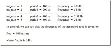
Timer I is in 8-bit auto-reload mode and the timer register is loaded with 50 !ls (count of 206). Thus a timer I interrupt is generated every 50 !ls. Inside the timer I interrupt service routine, a counter is incremented and its value compared to a global variable called int_rate. When the twoare equal the speaker output is changed. The frequency of the generated output waveform is then as follows (notice that the period is twice the timer count value since half of the period is off and the other half is on):

Sound Projects-0013

In general, we can say that the frequency of the generated tone is given by: freq = I0/int_rate where freq is in kHz.

In this project, variable int_rate is varied from I00 down to I, i.e. the frequency of the generated tone varies between I00 Hz and I0 kHz.

Timer 0 of the microcontroller is used to change the frequency of the tone by changing the value of variable int_rate. Timer 0 is in 8-bit auto-reload mode and the timer register is loaded with 56 so that it generates interrupts at every 200 !ls. Inside the timer 0 interrupt service routine a counter is used and variable int_rate is decremented by I when the counter counts by 200. Thus, variable int_rate will be decremented every 200 x 200 !ls = 40,000 !ls or 40 ms.

In summary, the frequency of the generated tone will vary every 20 ms from I00 Hz to I0 kHz. The result is that a siren type output will be generated on the speaker.

The following PDL describes the functions of the program:

Sound Projects-0014

Sound Projects-0015

Program Listing

The full program listing is shown in Fig. 4.7. Variable SPEAKER is assigned to bit 7 of port I. When the program starts, variables count and timer1_overlow are set to0. The speaker is then turned off. Timers 0 and I are initialized by calling function init_timers. The program then enters an endless loop and waits until the timer interrupts occur.

Inside the timer I interrupt service routine, variable count is incremented and compared to variable int_rate. When the twoare equal, count is reset to0 and the speaker output is complemented.

Inside the timer 0 interrupt service routine, variable timer1_overlow is incremented and when it reaches 200 (i.e. 200 x 200 !ls = 40 ms), it is reset to

0 and int_rate is decremented sothat a higher frequency tone could be generated by timer I. When int_rate reaches 0 it is reset back toI00 sothat the process can repeat.

Sound Projects-0016

Sound Projects-0017


Sound Projects:Two-tone Small Speaker Interface (Using the Timer Interrupt)

PROJECT 14 – Two-tone Small Speaker Interface (Using the Timer Interrupt)

Function

This project shows how we can interface our microcontroller to a small speaker type audible device and generate two different tones. When power is applied to the circuit, a continuous single tone of frequency I kHz is output to the speaker. When a push-button switch is pressed, the tone frequency is changed to 500 Hz. Timer I interrupt of the microcontroller is used to generate the time delay required for the tones.

Circuit Diagram

The circuit diagram of this project is the same as the one in Project I2 (i.e. Fig. 4.3) except that the buzzer is replaced with a small speaker. Bit 7 of port I is connected directly to a small speaker via a MOSFET transistor. The port output is in voltage mode so that the buzzer will turn on when the port output is at logic HIGH ( + 5 V). Bit 0 of port 3 is connected to a push-button switch, which is normally held at logic HIGH by the pull-up resistor R2.

Program Description

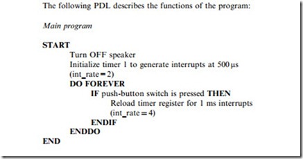
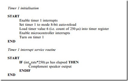
The speaker is initially turned OFF. Timer I of the microcontroller is then initialized to generate a continuous tone with a frequency of I kHz, as in Project I3. The push-button switch is then checked and when the switch is pressed, the timer register value is doubled, i.e. the interrupt interval is increased from 500 !ls to I ms. A waveform with a I ms on and I ms off time has a frequency of 500 Hz.

The following PDL describes the functions of the program:

Sound Projects-0009

Sound Projects-0010

Program Listing

The full program listing is shown in Fig. 4.6. When the program starts a variable called count is set to0 and the speaker is turned off. Timer I is then initialized with the int_rate=2 sothat interrupts are generated every 500 !ls, i.e. an output frequency of I kHz. The state of the push-button switch is then checked. If the switch is pressed, the interrupt rate, int_rate, is changed to4 so that interrupts will be generated at every 4 x 250 !ls = I ms i.e. the frequency of the generated waveform is changed to 500 Hz (I ms on time and I ms off time).

timer1() is the timer I interrupt service routine with interrupt number 3. In this routine, variable count is incremented and compared with the int_rate. When the two are equal, the speaker output is complemented, i.e. if the speaker is on it is turned off, and if off it is turned on.

The frequency of the generated tones can easily be changed by loading a different value into the timer register or by changing the value of variable int_rate.


Sound Projects:Small Speaker Interface (Using the Timer Interrupt)

PROJECT 13 – Small Speaker Interface (Using the Timer Interrupt)

Function

This project shows how we can interface our microcontroller to a small speaker type audible device. In this project a continuous single tone output is produced on the speaker when a push-button switch is activated. Timer interrupt of the microcontroller is used to generate the time delay required for the tone. In this project the frequency of the generated tone is 1 kHz (i.e. a period of 1 ms).

Circuit Diagram

The circuit diagram of this project is same as the one in Project 12 (i.e. Fig. 4.3) except that the buzzer is replaced with a small speaker. Bit 7 of port 1 is connected directly to a small speaker via a MOSFET transistor. The port output is in voltage mode so that the speaker will turn on when the port output is at logic HIGH ( + 5 V). Bit 0 of port 3 is connected to a push-button switch which is normally held at logic HIGH by the pull-up resistor R2.

Program Description

The speaker is initially turned OFF. The push-button switch is then checked and when the switch is pressed, timer 1 of the microcontroller is initialized to generate interrupts at regular intervals. When a timer interrupt is generated the state of the timer is reversed. i.e. if the timer is on, it is turned off and if it is off, it is turned on. The frequency of this waveform is set to be in the audible range and thus it generates an audible sound on the speaker.

The following PDL describes the functions of the program:

Sound Projects-0005

Program Listing

The full program listing is shown in Fig. 4.4. When the program starts a variable called count is set to 0 and the speaker is turned off. The status of the push-button switch is then checked. If the switch is pressed, function init_timer is called to initialize timer 1 of the microcontroller.

Init_timer routine enables timer 1 of the microcontroller, sets timer 1 into 8-bit auto-reload mode (mode 2) and loads the timer counter with 6 so that a timer overflow will occur after 250 counts (i.e. when the timer rolls over from 256 to 0). The timer is then automatically reloaded with the same value. With a microcontroller operating at 12 MHz, the timer clock cycle time is 1 )ls since the clock is divided by 12 internally. Thus, a timer interrupt will be generated after every 250 )ls. When a timer interrupt is generated, control is directed to the interrupt service routine (ISR) called timerI( ) as shown in Fig. 4.4. Note that timer 1 interrupt number is 3. The ISR increments the global variable count. Variable count reaches 2 after twointerrupts, i.e. after 500 )ls has

Sound Projects-0006

Sound Projects-0007

elapsed. The state of the speaker is then changed after 500 !ls. As shown in Fig. 4.5, the period of the generated waveform is thus I ms (500 !ls ON time and 500 !ls OFF time, i.e. a frequency of I kHz).

You can change the frequency of the tone easily by loading a different value intothe timer register.

Components Required

In addition to the components used for the basic microcontroller circuit, the following components will be required:

Sound Projects-0008


Sound Projects:Simple Buzzer Interface

In this chapter we shall be looking at how we can interface our microcontroller to sound generating devices. Sound projects are based on audible devices and these devices have many applications in electronics, ranging from warning devices, burglar alarms, speech processing applications, electronic organs and so on.

Electronic sound generation requires an electronic audible device. There are several such devices available:

• Piezo sounders: these devices operate by an external DC source. An internal oscillator applies an AC signal to a piezo substrate and this causes alternating deformation of the disc, producing sound output. These devices require about 8 to 20 mA current and generate a sound output of 80 to 100 dBA, at a distance of approximately 30 cm. The frequency response of these devices is in a narrow band, generally in the region 3 to 5 KHz. Piezo sounders usually emit a single tone but some models can emit two or more tones and can also provide pulsed tone outputs. Piezo sounders operate over a wide DC voltage range and as a result of this, they are widely used in small portable electronic equipment.

• Buzzers: these are mechanical devices which produce sound via a magnetized arm repeatedly striking a diaphragm. These devices operate with a DC voltage and the current requirement is small, generally in the region of 10 mA. Buzzers generate a ‘buzzing’ noise (single tone) in the frequency range 300 to500 Hz. Buzzers are small devices and they can be either panel mounted or PCB mounted.

• Sounders: these audible devices generally operate with a DC voltage in the

range 3 to 24 V. The current requirement is around 15 mA. The sound output of sounders is single tone at 3 KHz or less, with 80 to 85 dBA at a distance of 30 cm.

• Transducers: these devices generally operate with a small DC voltage

(around 3 V) and require external drive circuitry. Sound output is 85 dBA or more at a distance of 30 cm. The resonant frequency of transducers is 3 KHz or less. These devices are usually used as mini speakers in PCB mounted applications.

• Coi/ type: these devices operate by a coil attracting and repelling a magnetized diaphragm. The principle of operation is the same as a loudspeaker and in fact these are tiny speakers. An external drive circuit is required togenerate sound. Coil type audible devices are generally used when multitone sound or speech is required.

In this chapter we shall be interfacing our microcontroller to simple buzzers and also to more complex audible devices.

PROJECT 12 – Simple Buzzer Interface

Function

This project shows how we can interface our microcontroller to a buzzer. When a push-button switch is pressed (e.g. simulating a burglary), the buzzer will turn on and off 30 times and then stop.

Circuit Diagram

The circuit diagram of this project is shown in Fig. 4.1. Bit 7 of port 1 is connected directly to a small buzzer. This type of connection is possible if the current requirement of the buzzer is not more than about 20 mA. The port output is in current source mode so that the buzzer will turn on when the port output is at logic LOW (0 V). Bit 0 of port 3 is connected to a push-button switch which is normally held at logic HIGH by a pull-up resistor.

Program Description

The buzzer is initially turned OFF. The push-button switch is then checked and when the switch is pressed, the buzzer is turned on and off 30 times, with a

1 second delay between each output. The following PDL describes the functions of the program:

Sound Projects-0000

Sound Projects-0001

Program Listing

The program listing is given in Fig. 4.2. Variable BUZZER is defined as bit 7 of port 1. Similarly, variable PUSH_BUTTON is defined as bit 0 of port 3. When the program starts, BUZZER is set toOFF, where OFF is defined as logic HIGH. The state of the PUSH_BUTTON switch is then checked continuously in a loop. When the switch is pressed (PUSH_BUTTON = O), a for loop is set to repeat 30 times. Inside this loop the buzzer is turned ON and OFF with a 1 second delay between each output.

Using Higher Current Buzzers

The buzzer used in Fig. 4.1 is assumed to draw not more than 20 mA and thus we can connect the buzzer directly to the microcontroller. For buzzers that

Sound Projects-0002

operate with higher currents it will be necessary touse a circuit similar toFig.

4.3. In this circuit a MOSFET n-channel transistor is used as a switch. The buzzer is connected to the drain (D) input and the gate (G) input is driven directly from the microcontroller. The current drawn by the gate input is practically zero. A VN66AFD type MOSFET can be used to switch currents up toabout 2 A.

Sound Projects-0003

Components Required

In addition to the components used for the basic microcontroller circuit, the following components will be required:

Sound Projects-0004