Rs232 Serial Communication Projects:Input/Output Example Using the RS232 Port

PROJECT 23 – Input/Output Example Using the RS232 Port

Function

This project shows how we can input and output serial data using the built-in C functions. In this example, the user is prompted to enter a character through the RS232 terminal. The program then finds the next character (i.e. increments the character by one) and outputs it to the user’s terminal.

Circuit Diagram

The circuit diagram of this project is the same as in Project 22 (i.e. Fig. 6.5).

Program Description

The RS232 serial port is initialized to operate at 2400 baud. The user is then prompted to enter a character. This character is incremented by one and sent to the serial output port.

The following PDL describes the functions of the program:

Rs232-Serial-Communication-Projects-[7]

Rs232-Serial-Communication-Projects-[5]

Rs232-Serial-Communication-Projects-[8]

Program Listing

The program listing is shown in Fig. 6.8. Function serial_init initializes the serial port for operation at 2400 baud with a 12 MHz crystal. Built-in function printf is used toprompt the user to enter a character. A character is then read from the user’s terminal using the standard C built-in function getchar and this character is stored in a variable called c. Finally, this character is incremented by one and is output to the RS232 port using function printf. The above process is repeated indefinitely. This program occupies 1164 bytes of memory.

Input/Output Without Using the Built-in Functions

The above program uses the standard C built-in functions printf and getchar. As a result the program is big. An example program is given in Fig. 6.9 which does not use these built-in functions and thus occupies much less space in memory.

Function serial_init is the same as before but note that the serial port interrupts are enabled (EA = 1 and ES = 1). Function send_serial sends a null-terminated string to the serial output port. Similarly, function send_l_char sends a single character to the serial port. Serial data is read in via the serial port interrupt service routine (serial). Whenever a character is transmitted or received, the interrupt service routine is activated automatically. The interrupt number of the serial port is 4. Here, the receive interrupt register (RI) is checked and a character is assumed to be received from the serial port if RI is non-zero. The received character is copied from SBUF to a variable called received_character.

The main program calls function send_serial todisplay the message ‘Enter a character’. If a character is received, this character is echoed on the user’s terminal and the next character is displayed by incrementing and outputting the variable received_character. Function send_l_char is then used tosend a carriage return and line feed after each output.

Rs232-Serial-Communication-Projects-[14]

Rs232-Serial-Communication-Projects-[4]Rs232-Serial-Communication-Projects-[17]


Rs232 Serial Communication Projects:Output a Simple Text Message from the RS232 Port

PROJECT 22 – Output a Simple Text Message from the RS232 Port

Function

This project shows how we can interface our microcontroller to an external RS232 compatible device (e.g. an RS232 visual display unit, or COM1 or COM2 port of a PC) and send a text message to this device. The text message ‘THIS IS AN RS232 TEST MESSAGE’ is sent out continuously from the microcontroller. The frame format used in this project is 2400 baud, 8 data bits, noparity, and 1 stop bit.

Rs232-Serial-Communication-Projects-

Circuit Diagram

The block diagram of Project 22 is shown in Fig. 6.4. The TXD pin of the microcontroller is connected to the MAX232 Maxim voltage converter IC and the output of this IC can be connected to the input of a COM1 (or COM2) port of a PC, or to the input of an RS232 visual display unit. Similarly, the output of the external RS232 device is connected to the RXD input of the micro- controller via the MAX232 IC. A terminal emulation software can be activated on the PC to receive and display any data arriving at its serial port.

The complete circuit diagram of this project is shown in Fig. 6.5. Pin P3.1 of the microcontroller (TXD) is connected to pin 10 of the MAX232 converter IC. Pin 7 of this IC is connected to the external RS232 compatible serial device which is to receive and display our text message. Similarly, the output of the RS232 device is connected to pin 8 input of the MAX232 IC and pin 9 output of this IC is connected to pin 2 (RXD) serial input of the microcontroller. Correct operation of MAX232 requires four external capacitors to be connected as shown in the figure.

Program Description

The program initializes the RS232 port of the microcontroller and then sends a test message tothe port.

The following PDL describes the functions of the program:

Rs232-Serial-Communication-Projects-[2]

Rs232-Serial-Communication-Projects-[10]

Program Listing

The program listing is given in Fig. 6.6. Notice that the standard input/output library ‘stdio.h’ is included at the top of the program. The main program calls function serial_init which initializes the RS232 port to 2400 baud and enables transmissions. Standard C function printf is used tosend the serial data tothe RS232 port. A carriage return and line feed pair (‘n’) are sent after each output.

It is important to notice that this simple program occupies about 1094 bytes in the memory of the microcontroller. This is because the printf function is a complex library function and is implemented in a large number of instructions. A simple function can be developed to emulate some of the functionalities of printf so that the output operations can be performed with less memory as described below.

Rs232-Serial-Communication-Projects-[6]

A Simple Serial Output Function

The 89C2051 microcontroller is equipped with 2 Kbytes of memory. It was shown in the previous example that using the built-in printf function causes a large part of this memory to be used, leaving little space for other operations. Figure 6.7 shows a program listing that performs serial output functions without using the printf function and the complete program occupies about 400 bytes of memory. In this program, the serial transmit register of the microcontroller (SBUF) is used to send out data directly. Function send_serial transmits a null-terminated string to the RS232 port of the microcontroller. The program waits until the transmit register is empty (TI = 1) before sending out the next character. In this example, the string ‘ANOTHER TEST’ is output continuously. Notice that calling this function with variable crlf causes a carriage return and line feed to be output at the end of the test message.

Components Required

The following components will be required in addition to the standard microcontroller components:

Rs232-Serial-Communication-Projects-[11]


Rs232 Serial Communication Projects

RS232 is a serial communications standard which enables data to be transferred in serial form between two devices. Data is transmitted and received in serial ‘bit stream’ from one point to another. Standard RS232 is suitable for data transfer to about 50 m, although special low-loss cables can be used for extended distance operation. Four parameters specify an RS232 link between twodevices. These are baud rate, data width, parity, and the stop bits, and are described below:

• Baud rate: the baud rate (bits per second) determines how much informa- tion is transferred over a given time interval. A baud rate can usually be selected between 110 and 76 800 baud, e.g. a baud rate of 9600 corresponds to9600 bits per second.

• Data width: the data width can be either 8 bits or 7 bits depending upon the nature of the data being transferred.

• Parity: the parity bit is used to check the correctness of the transmitted or

received data. Parity can either be even, odd, or no parity bit can be specified at all.

• Stop bit: the stop bit is used as the terminator bit and it is possible to specify

either one or two stop bits.

Serial data is transmitted and received in frames where a frame consists of:

• 1 start bit

• 7 or 8 data bits

• optional parity bit

• 1 stop bit

In many applications 10 bits are used to specify an RS232 frame, consisting of 1 start bit, 8 data bits, no parity bit, and 1 stop bit. For example, character ‘A’ has the ASCII bit pattern ‘01000001’ and is transmitted as shown in Fig. 6.1 with 1 start bit, 8 data bits, noparity, and 1 stop bit. The data is transmitted least significant bit first.

When 10 bits are used tospecify the frame length, the time taken to transmit or receive each bit can be found from the baud rate used. Table 6.1 gives the time

SNAG-0065_thumb

RS232 Connectors

As shown in Fig. 6.2, two types of connectors are used for RS232 commu- nications. These are the 25-way D-type connector (known as DB25) and the 9-pin D-type connector (also known as DB9). Table 6.2 lists the most commonly used signal names for both DB9 and DB25 type connectors. The used signals are:

SNAG-0066_thumb

SNAG-0067_thumb

SG: signal ground. This pin is used in all RS232 cables.

RD: received data. Data is received at this pin. This pin is used in all two-

way communications.

TD: transmit data. Data is sent out from this pin. This pin is used in all

two-way communications.

RTS: request tosend. This signal is asserted when the device requests data to

be sent.

CTS: clear tosend. This signal is asserted when the device is ready toaccept

data.

DTR: data terminal ready. This signal is asserted toindicate that the device is

ready.

DSR: data set ready. This signal indicates, by the device at the other end,

that it is ready.

CD: carrier detect. This signal indicates that a carrier signal has been

detected by a modem connected to the line.

In some RS232 applications it is sufficient to use only the pins SG, RD, and TD. Also, in some applications (e.g. when two similar devices are connected together) it is necessary to twist pins RD and TD so that the transmit pin of one device is connected to the receive pin of the other device and vice versa.

RS232 Signal Levels

RS232 is bi-polar and a voltage of +3 to +12 V indicates an ON state (or SPACE), while a voltage of -3 to -12 V indicates an OFF state (or MARK). In practice, the ON and OFF states can be achieved with lower voltages.

SNAG-0068_thumb

Standard TTL logic devices, including the 89C2051 microcontroller, operate with TTL logic levels between the voltages of 0 and +5 V. Voltage level converter ICs are used to convert between the TTL and RS232 voltage levels. One such popular IC is the MAX232, manufactured by MAXIM, and operaters with +5 V supply. The MAX232 is a 16-pin DIL chip incorporating tworeceivers and two transmitters (see Fig. 6.3) and the device requires four external capacitors for proper operation.

The 89C2051 microcontroller can output TTL level RS232 signals from its TXD (or pin P3.1) pin and it can receive TTL level RS232 signals from its RXD (or pin P3.0) pin. The microcontroller can be connected to external RS232 compatible equipment via a MAX232 type voltage converter IC.

Controlling the RS232 Port

Before the serial port can be used it is necessary to set various registers:

SCON: this is the serial port control register. It should be set to hexade- cimal 0x50 for 8-bit data mode.

TMOD: this register controls the timers for baud rate generation and it should be set tohexadecimal 0x20 to enable timer 1 to operate in 8-bit auto-reload mode.

TH1: this register should be loaded with a constant so that the required baud rate can be generated. Table 6.3 shows the values to be loaded

into TH1 and the corresponding baud rates for two different clock rates.

TR1: this register starts/stops the timer and it should be set to 1 to start timer 1.

TI: this register should be set to1 toindicate ready totransmit.

SNAG-0069_thumb


Temperature Projects:Digital Thermometer with Centigrade/ Fahrenheit Output

PROJECT 18 – Digital Thermometer with Centigrade/ Fahrenheit Output

Function

This project is similar to Project I7, but in addition the outputs can display the temperature in both Centigrade (oC) and Fahrenheit (oF). An SPDT switch is connected to bit 3 of port 3 and the output of this switch is normally held at logic high with a pull-up resistor. In this state the output display is in oC. When the switch is pressed, the display changes toshow the temperature in oF. The rest of the project is the same as Project I7, i.e. the temperature is measured with a DSI620 type thermometer IC and the output is displayed on three TIL3II type alphanumeric displays.

Circuit Diagram

The block diagram of this project is shown in Fig. 5.5. The circuit diagram is similar to the circuit of Project I7 with the addition of an SPDT switch to bit 3 of port 3. The temperature is sensed by the DSI620 thermometer IC and the output is displayed either in oC or in oF based upon the state of the SPDT switch. The full circuit diagram is shown in Fig. 5.6.

Program Description

The program is the same as the one in Project I7 except that the state of the SPDT switch is monitored and when the switch is pressed, the temperature is converted from oC to oF and then displayed accordingly. Negative tempera- tures are displayed by inserting the leading letter ‘E’.

Temperature-Projects-0037_thumb

Temperature-Projects-0038_thumb

Program Listing

The full program listing of this project is shown in Fig. 5.7. Only the parts which are different from Project I7 are described here. Variable mode is assigned to bit 3 of port 3. The value of mode is checked in function display_temperature. If mode is zero(i.e. in Fahrenheit mode), the temperature is converted to oF by multiplying by I.8 and adding 32. The final temperature is then displayed as in Project I7.

Components Required

In addition to the standard components required by the microcontroller, the following components will be required for this project:

Temperature-Projects-0039_thumbTemperature-Projects-0040_thumbTemperature-Projects-0041_thumbTemperature-Projects-0042_thumb

Temperature-Projects-0043_thumb


Temperature Projects:Digital Thermometer With High and Low Alarm Outputs

PROJECT 20 – Digital Thermometer With High and Low Alarm Outputs

Function

This project is similar to Project I9 except that the DSI620 is programmed so that a buzzer connected to the TCOM output of DSI620 turns on when the temperature is equal to or greater than TH and it then turns off only when the temperature drops below or equal to TL. In this project, TL is set to 25oC and TH is set to30oC.

Temperature-Projects-0045_thumb

Temperature-Projects-0046_thumbTemperature-Projects-0047_thumbTemperature-Projects-0048_thumbTemperature-Projects-0049_thumb
Circuit Diagram

The circuit diagram of this project is same as in Fig. 5.8 except that the MOSFET transistor is connected to pin 5 (TCOM) of the DSI620 instead of pin 7 (see block diagram, Fig. 5.I0). A small buzzer is connected to the TCOM output of the DSI620 via a MOSFET power transistor. Normally the TCOM output is at logic low level and this output goes to logic high when the temperature exceeds the value TH (stored in the non-volatile memory of the DSI620) and then goes back to logic low when the temperature is equal to or less than TL.

Program Description

Temperature-Projects-0050_thumb

The program is basically the same the as the one in Project I9 except that the temperature high limit (TH) is set to 60 so that THIGH output goes high when the temperature is equal to or exceeds 30oC and TL is set to50 sothat the TCOM output goes back to 0 when the temperature drops to 25oC or below, i.e. the buzzer will turn on when the temperature reaches 30oC and it will go off only when the temperature drops to 25oC or below.

Program Listing

The full program listing is shown in Fig. 5.II. This listing is the same as the listing in Project I9 with the addition of a function called set_tlow which sets the low limit (TL) of the DSI620.

Required Components

This project uses the same components as in Project I9.


Temperature Projects:Digital Thermometer with High Alarm Output

PROJECT 19 – Digital Thermometer with High Alarm Output

Function

This project is similar to Project I7 but a buzzer is connected to the THIGH output of the DSI620 thermometer IC, via a MOSFET transistor. When the temperature exceeds a preset value the buzzer turns on and stays on as long as the temperature is above this value. In this project the alarm sounds when the temperature is equal to or greater than 25oC.

Circuit Diagram

The circuit diagram of this project is shown in Fig. 5.8. The DSI620 ther- mometer IC and the TIL3II displays are connected as in Projects I7 and I8. A small buzzer is connected to the THIGH output of the DSI620 via a MOSFET power transistor. Normally the THIGH output is at logic low level and this output goes to logic high when the temperature exceeds the value TH stored in the non-volatile memory of the DSI620.

Program Description

The program is basically the same as the one in Project I7 except that the temperature high limit (TH) is set to 50 so that the THIGH output goes high when the temperature is equal to or exceeds 25oC and this turns on the buzzer togive a warning sound.

Program Listing

The full program listing is shown in Fig. 5.9. In addition to the program listing of Project I7, a function called set_thigh is added toload the temperature high limit. This function sends protocol number 0I to the DSI620 and then sends the data value 50 toset TH to25oC.

Required Components

In addition to the components used for Project I7, a MOSFET transistor (e.g. VN66AFN) and a small buzzer will be required for this project.

Temperature-Projects-0044_thumb


Temperature Projects:Using a Digital Temperature Sensor

PROJECT 17 – Using a Digital Temperature Sensor

Function

This project shows how we can interface a DSI620 type digital temperature sensor to our microcontroller. The ambient temperature is measured con- tinuously and then displayed in degrees centigrade on three TIL3II type alphanumeric displays. Positive temperature is displayed from 0oC toI25oC. Negative temperature is displayed with a leading letter ‘E’ in the range down to -55oC.

Circuit Diagram

The block diagram of this project is shown in Fig. 5.I. DSI620 is a digital IC temperature sensor which measures the ambient temperature and provides the output as 9 bits of digital serial data. The microcontroller extracts the temperature data from the DSI620 and then displays the temperature on three TIL3II type alphanumeric displays.

Before describing the circuit diagram in detail, it is useful to look at the operation of the DSI620 temperature sensor IC.

Temperature-Projects-0024_thumb

DS1620 Digital Thermometer IC

DSI620 is a digital thermometer and thermostat IC that provides 9 bits of serial data to indicate the temperature of the device. The pin configuration of the DSI620 is shown in Fig. 5.2. VDD is the power supply which is normally connected to a +5 V supply. DQ is the data input/output pin. CLK is the clock input. RST is the reset input. The device can alsoact as a thermostat. THIGH is driven high if the DSI620’s temperature is greater than or equal to a user defined temperature TH. Similarly, TLOW is driven high if the DSI620’s temperature is less than or equal to a user defined temperature TL. TCOM is driven high when the temperature exceeds TH and stays high until the temperature falls below TL. User defined temperatures TL and TH are stored in non-volatile memory of the device so that they are not lost even after removal of the power.

Data is output from the device as 9 bits, with the LSB sent out first. The temperature is provided in 2’s complement format from -55oC to +I25oC, in steps of 0.5oC. Table 5.I shows the relationship between the temperature and data output by the device.

Temperature-Projects-0025_thumb

Temperature-Projects-0026_thumb

Data input and output is through the DQ pin. When RST input is high, serial data can be written or read by pulsing the clock input. Data is written or read from the device in two parts. First, a protocol is sent and then the required data is read or written. The protocol is 8-bit data and the protocol definitions are given in Table 5.2. For example, to write the thermostat value TH, the hexadecimal protocol data 0I is first sent to the device. After issuing this

Temperature-Projects-0027_thumb

command, the next nine clock cycles clock in the 9-bit temperature limit which will set the threshold for operation of the THIGH output.

For example, the following data (in hexadecimal) should be sent to the device to set it for a TH limit of +50oC and TL limit of +20oC and then subsequently to start the conversion:

Temperature-Projects-0028_thumb

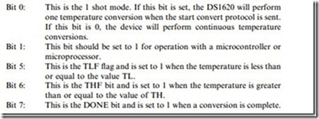
A configuration/status register is used to program various operating modes of the device. This register is written with protocol 0C (hex) and the status is read with protocol AC (hex). Some of the important configuration/status register bits are as follows:

Temperature-Projects-0029_thumb

The complete circuit diagram of this project is shown in Fig. 5.3. Bit 2 of port 3 is connected to the RST input of DSI620, bit I is connected to the clock input and bit 0 of port 3 is connected to the DQ pin of the DSI620. Three TL3II type alphanumeric displays are connected to port I of the microcontroller. Digit I is controlled from bit 7 of port I, digit 2 from bit 6 of port I, and digit 3 from bit 5 of port I.

Program Description

The program reads the temperature from the DSI620 thermometer IC and displays the temperature on three TIL3II type displays continuously with I second delay between each displayed output. The following PDL describes the operation of the program:

Temperature-Projects-0030_thumb

Temperature-Projects-0031_thumb

Program Listing

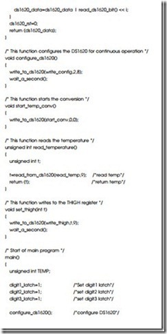
The full program listing is given in Fig. 5.4. The display digit latches and the DSI620 control lines are assigned to bit variables at the beginning of the program. Also the used protocols are defined and assigned to global variables. For example, read_temp is assigned tohexadecimal number AA, start_conv is assigned tohexadecimal number EE and so on.

When the program starts, the digit latches digit1_latch, digit2_latch, and digit3_latch are all set to I to avoid any erroneous writes to the displays. A function conigure_ds1620 is then called to set the configuration register/status

Temperature-Projects-0032_thumb

Temperature-Projects-0033_thumb

Temperature-Projects-0034_thumb

Temperature-Projects-0035_thumb

for continuous operation. Temperature conversion is then started by calling the function start_temp_conversion. This function sends protocol EE (hex) to the DSI620. An endless loop is then formed using the for statement with no parameters. Inside this loop, function read_temperature reads the 9-bit temperature value and returns in variable TEMP. Function display_temperature displays the temperature on the three TIL3II displays. This loop is repeated with about a I second delay between each output.

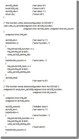
Function read_temperature returns the temperature tothe calling program as an unsigned integer. This function calls function read_from_ds1620 with the argument AA (in hex) toget the temperature. Function read_from_ds1620 is a general routine which reads data from the DSI620. This function sends a protocol data to the DSI620 and then reads data bytes from the DSI620 corresponding to the sent protocol. The RST input of the device is first set to I. A for loop is then formed to iterate eight times to send serial protocol data to the DSI620. LSB is sent out first. Local variable this_bit stores the bit to be sent out at each iteration. Another for loop reads data from the DSI620 and stores this data in variable ds1620_data. At the end of the read cycle the RST input is set back to0 and the data in ds1620_data is returned tothe caller.

Function write_to_ds1620 is a general function and it sends a protocol, followed by data bits, to the DSI620. The RST input of the DSI620 is first set toI. A for loop is then formed to iterate eight times and the protocol bits are sent out serially to the DQ input of the DSI620. Variable this_bit stores the bit to be sent out at each iteration. After this, another for loop sends out the required number of data bits to the DSI620. At the end of the write cycle, the RST input is returned to0.

Function display_temperature receives the temperature data as its argument and displays the temperature on the three TIL3II type alphanumeric displays. If the temperature is negative, the first display digit is set todisplay letter ‘E’. The temperature value tobe displayed is divided by 2 since the temperature is returned by the DSI620 in 0.5oC intervals. For example, a reading of decimal I00 corresponds to 50oC. Each digit is displayed after converting the data to decimal format.

Components Required

In addition to the basic components required by the microcontroller, the following components will be required for this project:

Temperature-Projects-0036_thumb


Temperature Projects:Using Analogue Temperature Sensor IC with A/D Converter

PROJECT 21 – Using Analogue Temperature Sensor IC with A/D Converter

Function

This project shows how we can connect an analogue-to-digital (A/D) converter IC to our microcontroller. In this project, an analogue temperature sensor IC (LM35DZ) is used and its output is connected to an 8-bit A/D converter (ADC0804). The temperature is then displayed every second on a TSM5034 type 4-digit display. The block diagram of this project is shown in Fig. 5.I2.

The A/D converter shown in this project can be connected to any kind of analogue voltage. For example, a digital voltmeter can be constructed easily by connecting the A/D converter input to an external voltage which is to be measured.

Circuit Diagram

Before looking at the circuit diagram of this project, it will be useful if we look at the ways an A/D converter can be connected to a microcontroller. There are many types of A/D converters available on the market. Some converters provide serial output data such that the output data is obtained from the converter each time a clock pulse is sent to the converter. These converters are very slow and are generally used where the speed of conversion is not important and where space saving is required. Serial A/D converters interface to a microcontroller by using only a few pins.

Standard A/D converters are generally used in medium- and high-speed applications. An example of such an A/D converter is the ADC0804,

Temperature-Projects-0051_thumb

Temperature-Projects-0052_thumbTemperature-Projects-0053_thumbTemperature-Projects-0054_thumbTemperature-Projects-0055_thumb

manufactured by the National Semiconductor Corporation. The conversion time of this A/D converter is I00 !ls. As shown in Fig. 5.I3, these converters interface to the microcontroller using the following pins (only the pins used in a standard application are shown):

Temperature-Projects-0056_thumbTemperature-Projects-0057_thumb

RD is the read data control pin and when RD is low (logic 0), output data appears on the eight output pins. When RD is high (logic I), the output is not available.

WR input is normally at logic high and this input should be set to low and then high again for a conversion to start.

INTR is the interrupt output of the A/D converter. A high to low pulse is generated on this pin when a conversion is complete. This output is usually used to generate an interrupt in the microcontroller so that the converted data can be read.

ADC0804 contains an internal oscillator and it is required to connect an external resistor and a capacitor to pins CLK R and CLK IN to start the oscillator.

VIN+ is the pin where the analog input voltage should be applied.

Temperature-Projects-0058_thumb

• Set WR and RD high

• Start conversion by setting WR low

• Set WR back tohigh

• Detect end of conversion when INTR goes low (usually by interrupt)

• Set RD low and read data from DB0 to DB7

• Set RD high

The above process is of course repeated when more than one conversion is required.

Figure 5.I4 shows the full circuit diagram of Project 2I. Data and clock inputs of the TSM5034 are connected to bits I and 0 of port 3 respectively. The eight

data outputs of the ADC0804 are connected to port I. RD input is connected to bit 2 of port 3. WR is connected to bit 4 of port 3. The interrupt output, INTR, of the A/D converter is connected to bit 3 of port 3 which is the external interrupt I (INTI) pin of the microcontroller. Analogue input voltage is applied to pin 6 of the A/D converter and this input can be connected to any kind of analogue voltage which is to be measured.

In this project, analogue data comes from an LM35DZ type IC analogue temperature sensor. LM35DZ is a simple temperature sensor IC. Pin I of the device is connected to a power supply (e.g. +5 V), pin 3 is connected to the ground. Pin 2 is the output and this output provides a voltage which is directly proportional to the measured temperature. The device can measure tempera- tures from 2oC up toI00oC (some types can measure a wider range) and the output voltage to temperature relationship is I0 mV/oC. For example, at 20oC the output is 200 mV. Similarly, at 35oC, the output voltage is 350 mV, and so on. Internal oscillator of the A/D converter is activated by connecting an external resistor and a capacitor to pins CLK R and CLK IN. Notice that bits 0 and I of port I are connected to +5 V using pull-up resistors. This is necessary in some applications since the output drivers at these pins are open drain (i.e. there are nointernal pull-up resistors).

Program Description

The display part of the program is as described in the light pro}ects section of the book. We shall therefore look at the way the A/D converter is controlled by the software. The following PDL describes the operation of the project:

Temperature-Projects-0059_thumb

Temperature-Projects-0060_thumb

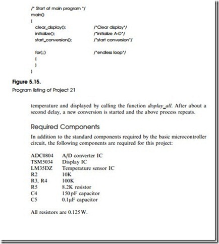
The program clears the display and then initializes the microcontroller so that external interrupts on pin INTI can be recognized. The A/D is then initialized and the conversion started. At the end of a conversion, an interrupt is generated by the A/D converter and execution jumps to the INTI service routine. Here, the converter data is read and displayed on the TSM5034 display. At the same time a new conversion is restarted.

Program Listing

The complete program listing is shown in Fig. 5.I5. Display clock and display data variables are assigned to pins 0 and I, respectively, of port 3 of the microcontroller. Similarly, A/D RD and A/D WR variables are assigned to pins 2 and 4 of port 3 of the microcontroller. When the program starts it first clears the display. Function initialize is then called toset the A/D RD and WR inputs (ADC_RD and ADC_WR) toI. External interrupt pin INT1 of the microcontroller is also set (IT1 = 1) in this routine to accept interrupts on high- to-low transition and the microcontroller is configured to accept interrupts (EA = 1). Function start_conversion is then called to start an A/D conversion. This function simply sets the WR input of the A/D to0 and then back toI. The program then enters an endless loop and waits for external interrupts on its INT1 pin.

INT1 has the interrupt number of 2. When a conversion is complete, control passes tothe interrupt service routine int1. In this routine, RD input of the A/D converter is set to 0 to enable the output buffers and then the digital data is read into port I of the microcontroller. The value read is then converted to true

Temperature-Projects-0061_thumb

Temperature-Projects-0062_thumbTemperature-Projects-0063_thumbTemperature-Projects-0064_thumb


Temperature Projects

Temperature measurement and control is one of the most common applications of microcontroller-based data acquisition systems. Four types of sensors are commonly used to measure temperature in commercial and industrial applications. These are thermocouples, resistive temperature devices (RTDs), thermistors, and integrated circuit (IC) temperature sensors. Each sensor has its unique advantages and disadvantages and by understanding how these sensors work, and what types of signal conditioning are required for each, we can make more accurate and reliable temperature measurement, monitoring, and control.

The typical characteristics of various temperature sensors are:

• Thermocouples: these are inexpensive, and the most common temperature sensors with a wide range of temperature range. Thermocouples work on the principle that when two dissimilar metals are combined, a voltage appears across the junction between the metals. By measuring this voltage, we can get a temperature reading. Different combinations of metals create different thermocouple voltages and there is a wide range of thermocouples available for different applications. Thermocouples generate very low voltages, typically 50 !lV/oC. These low-level signals require special signal conditioning to remove any possible noise. Thermocouples have non-linear relationships to the measured temperature and as a result it is necessary either to linearize the characteristics or to use look-up tables to obtain the actual temperature from the measured voltage.

• RTDs: an RTD is a resistor with its resistance changing with temperature.

The most popular type of RTD is made of platinum and has a resistance of I00 0 at 0oC. Because RTDs are resistive devices, a current must pass through the RTD to produce a voltage that can be measured. The change in resistance is very small (about 0.4 0/oC) and special circuitry is generally needed tomeasure the small changes in temperature. One of the drawbacks of RTDs is their non-linear change in resistance with temperature.

• Thermistors: thermistors are metal oxide semiconductor devices whose resistance changes with temperature. One of the advantages of thermistors is their fast responses and high sensitivity. For example, a typical thermistor

may have a resistance of 50 k0 at 25oC, but have a resistance of only 2 k0 at 85oC. Like RTDs, a current is passed through a thermistor and the voltage across the thermistor is measured. Thermistors are very non-linear devices and look-up tables are usually used to convert the measured voltage to temperature. Thermistors are very small and one disadvantage of this is that they can be self-heating under a large excitation current. This of course increases the temperature of the device and can give erroneous results.

• IC temperature sensors: integrated circuit temperature sensors are usually 3- or 8-pin active devices that require a power supply to operate and give out a voltage which is directly proportional to the temperature. There are basically two types of IC temperature sensor: analogue sensors are usually 3-pin devices and give out an analogue voltage of typically I0 mV/oC which is directly proportional to the temperature; digital temperature sensors provide 8- or 9-bit serial digital output data which is directly proportional tothe temperature.

In this chapter we shall be looking at how we can interface various temperature sensors to our microcontroller in order to measure and display the ambient temperature.


Programming Microcontrollers In C:Internet Web Sites of Microcontroller Compilers

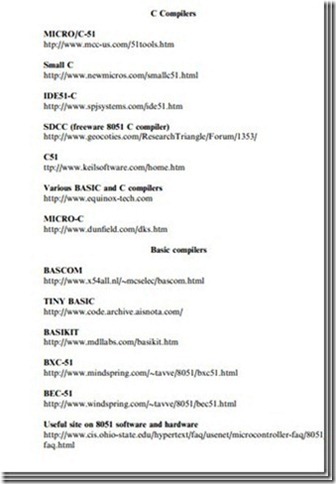
Internet Web Sites of Microcontroller Compilers

The amount of microcontroller software available on the Internet is huge and there are many different example programs. Internet web sites of some popular 8051 family microcontroller compilers and other useful sites are given below.

Programming-Microcontrollers-in-C-00[6]

Programming-Microcontrollers-in-C-00

Further Reading

The following books and reference manuals are useful in learning to program in C.

Programming-Microcontrollers-in-C-00[7]