7.4 WRITING PROGRAMS USING A CROSS-ASSEMBLER
This section describes a commercially available Z80 cross-assembler and the process of assembling a program. The description in the following sections is equally applicable to both assemblers and cross-assemblers; therefore, the term assembler should be interpreted as the representation of both. The assembly process is illustrated with a simple example from the last chapter.
7.4.1 Z80Cross-Assembler
The Z80 cross-assembler from 2500AD Software, Inc. * is one among several of such commercially available products. It includes two programs: X80 and LINK. In this assembler, translating mnemonics into binary code is a two-step process. The X80 translates the source file into modules of the Z80 code and generates two files: one is called the list (LST) file, and the other is called the object (OBJ) file. (This assembly process and the file names may vary slightly from assembler to assembler.) In addition to translating mnemonics, the assembler performs various functions, such as error checking and memory allocations.
The list (LST) file includes the source file plus the memory addresses and the Hex code of each instruction. This file is primarily used for documentation and may look like the hand-assembled file shown in the last chapter under program documentation or writing format.
The object file is an intermediate file that is used by the Link program to generate an executable binary COM (or TSK) file. The object file is necessary to combine different modules (or programs) and relocate the modules from one block of memory to another block of memory. In addition, the object file is used to generate the Hex file that can be used to transfer the program from the IBM PC to a Z80 single-board computer. This transfer of files among different systems is called downloading and uploading of files. This program assembly process is described in more detail in section 7.4.2 with an illustrative program. In addition, some editors also generate a back (BAK) file. When the user calls the source file for reediting, the editor copies the source file as the BAK file before the user begins to reedit, in case the user elects to retrieve the original file.
The complete assembly process on a software system such as the IBM PC can be summarized in the following steps:
1. Call up an editor program such as PC-Write or Wordstar, and write an assembly language program (statements) using an editor. Save the program. This is called the source program.
2. Call an assembler such as X80, use the source program as the input to the X80, and generate the object (OBJ) file and the list (LST) file.
3. If the assembler finds errors in the program, go back to Step 1 and correct the errors in the source program. Then repeat Step 2.
4. If the file needs to be transferred directly to a single-board computer, call the Link program (LlNK2) to generate the HEX file. This file is used to download the program from the IBM PC to the single-board computer if the download facility is available in the system. Otherwise, the Hex code can be loaded manually using the Hex keyboard into R/W memory of the single-board computer.
5. A binary executable file called COM or TSK file can be generated from the object file by using another Link program (LINK)). Generally, this step is unnecessary because the Z80 binary code cannot be executed by a system such as IBM PC.
Upon completion of the assembly process, the user can have the following files:
· Source file. This is the file written by the user using an editor. Generally, a file name can be eight characters long with an extension of three characters. The file name and the extension are separated by a period. For example, the file name can be DELAY 1.ASM; the extension ASM suggests that it is an assembly language file.
· OBJ file. This is a binary file generated by the assembler (X80) without any specific reference to the user memory. This file is used to generate an executable binary file called TSK (or COM) file and relocate the entire program for storage to specified memory locations.
· LST file. This is the list file generated by the assembler program (X80) for documentation purposes. It contains memory locations, Hex code, mnemonics, and comments. This file looks like a manually assembled program, as shown in Section 6.3.2.
· HEX file. This is generated by the Linker (LINK2) program and contains program code in hexadecimal notations. This file can be used for debugging the program and transferring files from one system to another system.
· TSK file. This is the executable file generated by the Linker (LINK1) program, and it contains binary code; this is the only file that can be understood and executed by the microprocessor.
· BAK file. When the source file is called for reediting, the previous file is saved as the BAK file.
4.4.2 Illustrative Program: Addition of Two Hexadecimal Numbers
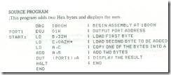
To illustrate how to write a source program, the example is taken from the last chapter, where it was assembled manually. The source program is written using an editor under the file name PROGRAM 1.ASM and assembled using the assembler X80 described earlier. The problem statement is repeated here for convenience; refer to section 6.3.1 for analysis.
PROBLEM STATEMENT
Write instructions to load the two hexadecimal numbers 32H and A2H into registers Band C, respectively. Add the numbers, and display the sum at the LED output port PORT1
This program illustrates the following assembler directives:
· ORG
The object code will be stored starting at the location 1800H•
· EQU
The program defines one equate: PORT1. In this program it would have been easier to write the port address directly with the instructions. However, equates are essential in development projects where hardware and software design are done concurrently, and they are also useful in long programs because they make it easy to change or redefine port addresses.
· Label
The program illustrates one label: START. This label represents the memory location I800H• In this illustration, the label is not particularly useful; generally, labels are used to specify Jump and Call addresses. In writing assembly language programs, it is convenient to identify a Jump or Call address by a label • because absolute addresses are not known in the beginning. Also, if any changes (deletions and additions) are made in the source program, the assembler will reassign all label addresses when it is reassembled. In manual assembly, the entire program must be rewritten with new addresses if any changes are to be made.
· End
The end of assembly.
TWO-PASS ASSEMBLER
To assemble the program, the assembler scans through the program twice; this is known as a two-pass assembler. In the first pass, the first memory location is determined from the ORG statement, and the counter known as the location counter is initialized. Then the assembler scans each instruction and records locations in the address column of the first byte of each instruction; the location counter keeps track of the bytes in the program. The assembler also generates a symbol table during the first pass. When it comes across a label, it records the label and its location. In the second pass, each instruction is examined, and mnemonics and labels are replaced by their machine codes.
ASSEMBLED LIST FILE
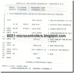
A list (LST) file generated from the source program (PROGRAM 1.ASM) by the X80 assembler is shown here.
The LST file has five columns: memory addresses, Hex codes, labels, mnemonics, and comments. It lists the memory addresses of the first byte of each instruction with its Hex codes on the same line. For example, the listing shows that the first memory address is 1800 and the first two Hex codes are 06 32; the next address is 1802. Therefore, it is understood that the memory address 1801 and holds the Hex byte 32. In addition to the program listing, the LST file includes the list of symbols, equates, and error messages.
Error Messages In addition to translating the mnemonics into object code, the assembler also gives error messages. These messages are of two types: terminal error messages and source program error messages. In the first case, the assembler is not able to complete the assembly. In the second case, the assembler lists the errors, but it is able to complete the assembly.
GENERATING COM (TSK) AND HEX FILES
This assembler has two Linker programs: LINK1 and LINK2; these programs use the OBJ file generated by the X80 program. The LINK1 generates the executable binary (TSK) file, and the LINK2 creates the HEX file that can be used to transfer the file from the IBM PC system to a single-board computer.
Precautions in Writing Programs Assembler programs are available from various software companies, and for the most part, they follow a similar format. However, we suggest the following precautions in writing assembly language programs.
-
Some assemblers impose a rigid format in which the source code must be written. For example, X80 must have a label starting in column 1. Similarly, it generates an error code if there is a space between operands. For example, in the first instruction (LD B, 32H), if there is a space between B and the comma, or between the comma and 32H, the X80 will generate an error message.
-
The letter following a number specifies the type of a number. A hexadecimal number is followed by the letter "H," an octal by letter "O," a binary by letter • "B." A number without a letter is interpreted as a decimal number.
-
Any Hex number that begins with A through F must be preceded by zero; otherwise, the assembler interprets the number as a label and gives an error message because it cannot find the label.
-
Some assemblers require a colon after a label.
-
When a 16-bit address is used in a mnemonic (such as Jump to 1850H), the X80 prints the address as 1850; however, it is stored in the reverse order in memory. Some assemblers print the address as 50 18.
USING AN INTEGRATED EDITOR-ASSEMBLER PROGRAM
An integrated editor-assembler software development package is available from CAMI Research" to assemble Z80 programs. One of the drawbacks of the assembly process described earlier is the need to go back and forth between the editor and the assembler until all the errors are corrected. This integrated software pack- age is menu driven, and the programs (editor, assembler, and linker) are integrated in one package. The program can identify errors and enable the user to edit them.

