PROJECT 10.3—Voltmeter with RS232 Serial Output
In this RTOS project, which is more complex than the preceding ones, the voltage is read using an A/D converter and then sent over the serial port to a PC. The project consists of three tasks: Live, Get_voltage, and To_RS232.
• Task Live runs every 200ms and flashes an LED connected to port RD7 of the microcontroller to indicate that the system is working.
• Task Get_voltage reads channel 0 of the A/D converter where the voltage to be measured is connected. The read value is formatted and then stored in a variable. This task runs every two seconds.
• Task To_RS232 reads the formatted voltage and sends it over the RS232 line to a PC every second.
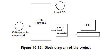
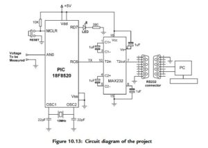
Figure 10.12 shows the block diagram of the project. The circuit diagram is given in Figure 10.13. A PIC18F8520-type microcontroller with a 10MHz crystal is used in this project (though any PIC18F-series microcontroller can be used). The voltage to be measured is connected to analog port AN0 of the microcontroller. The RS232 TX output of the microcontroller (RC6) is connected to a MAX232-type RS232-level converter chip and then to the serial input of a PC (e.g., COM1) using a 9-pin D-type connector. Port pin RD7 is connected to an LED to indicate whether the project is working.
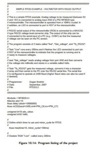
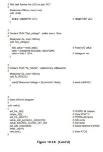
The program listing (RTOS3.C) of the project is given in Figure 10.14. At the beginning of the program, the A/D is defined as 10 bits, the clock is defined as 10MHz, and the RS232 speed is defined as 2400 baud. The RTOS timer and the minor_cycle are then defined using the #use rtos preprocessor command.
In the main part of the program PORTD is configured as output and all PORTD pins are cleared. Then PORTA is configured as input (RA0 is the analog input), the microcontroller’s analog inputs are configured, the A/D clock is set, and the A/D channel 0 is selected (AN0). The RTOS is then started by calling function rtos_run().
The program consists of three tasks:
• Task Live runs every 200ms and flashes an LED connected to port pin RD7 of the microcontroller to indicate that the project is working.
• Task Get_voltage reads the analog voltage from channel 0 (pin RA0 or AN0) of the microcontroller. The value is then converted into millivolts by multiplying by 5000 and dividing by 1024 (in a 10-bit A/D there are 1024 quantization levels, and when working with a reference voltage of þ5V, each quantization level corresponds to 5000/1024mV). The voltage is stored in a global variable called Volts.
• Task To_RS232 reads the measured voltage from common variable Volts and sends it to the RS232 port using the C printf statement. The result is sent in the following format:
Measured voltage ¼ nnnn mV
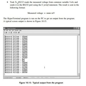
The HyperTerminal program is run on the PC to get an output from the program. A typical screen output is shown in Figure 10.15.
Using a Semaphore
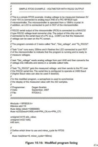
The program given in Figure 10.14 is working and displays the measured voltage on the PC screen. This program can be improved slightly by using a semaphore to
synchronize the display of the measured voltage with the A/D samples. The modified
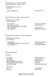
program (RTOS4.C) is given in Figure 10.16. The operation of the new program is as follows:
• The semaphore variable (sem) is set to 1 at the beginning of the program.
• Task Get_voltage decrements the semaphore (calls rtos_wait) variable so that task To_RS232 is blocked (semaphore variable sem ¼ 0) and cannot
send data to the PC. When a new A/D sample is ready, the semaphore variable is incremented (calls rtos_signal) and task To_RS232 can continue. Task To_RS232 then sends the measured voltage to the PC and increments the semaphore variable to indicate that it had access to the data. Task Get_voltage can then get a new sample. This process is repeated forever.
