BRANCH OPERATIONS
The branch instructions and their associated flags are the key to the power of a computer or its microprocessor. These instructions can change the sequence of execution based on certain data conditions indicated by the flags; thus, they are decision-making instructions.
The branch instructions are classified into three categories, as listed in
Chapter 6: (1) Jump instructions, (2) Call and Return instructions, and (3) Restart instructions. In this chapter, we concentrate on Jump instructions.
Jump Instructions
The Jump instructions can be divided into two groups: absolute jump and relative jump. In case of absolute jump, the operand specifies the 16-bit address to which the program sequence should be transferred; these are 3-byte instructions. The relative jump instructions are 2-byte instructions and contain an operand that specifies 8-bit displacement, forward or backward (in 2’s complement), in relation to the address of the jump instruction; these instructions are discussed in the next section.
The absolute jump instructions can be further classified into two groups: unconditional and conditional jump. The conditional jump instructions are implemented based on the status of four flags: S (Sign), Z (Zero), CY (Carry), and P/V (Parity/Overflow). Two instructions are associated with each flag: one for when the flag is set and the other for when it is reset. The list of Jump instructions · follows:
|
Opcode |
Operand |
Bytes |
Description |
|
JP |
16-bit |
3 |
Jump unconditional to memory location specified by the 16-bit operand. |
|
JP |
C, 16-bit |
3 |
Jump on carry to 16-bit address (CY = 1). |
|
JP |
NC, 16-bit |
3 |
Jump on no carry to 16-bit address (CY = 0). |
|
JP |
16-bit |
3 |
Jump on zero to 16-bit address (Z=1) |
|
JP |
NZ, 16-bit |
3 |
Jump on no zero to 16-bit address (Z = 0) |
|
JP |
M, 16-bit 3 |
3 |
Jump on minus to 16-bit address (S =1). |
|
JP |
P, 16-bit |
3 |
Jump on positive to 16-bit address (S = 0). |
|
JP |
PE, 16-bit |
3 |
Jump on parity even to 16-bit address (P/V = 1). |
|
JP |
PO, 16-bit |
3 |
Jump on parity odd to 16-bit address (P/V = 0). |
General Characteristics
1. The Jump (JP) instructions are 3-byte instructions. The second byte specifies the low-order address, and the third byte specifies the high-order address.
2. A conditional jump instruction checks for the appropriate flag. If the condition is true, the program sequence is changed to the memory location specified by the operand; otherwise, the execution continues to the next instruction.
3. The Jump instructions do not affect any flags.
Example
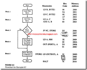
Write instructions to load tow Hex bytes BYTE1 and BYTE2 into registers B and C, respectively, and add the bytes . If the sum is larger than 8 bits , display 00H as the overload condition at output port PORT1 , and clear the memory location OUTBUF ; otherwise , store the sun in memory location OUTBUF . Draw a flowchart , and assemble the program starting at location 2000H. the data bytes and the labels are defined as follows:
BYTEl = 9AH, BYTE2 = A7H, PORTl = 0lH, and OUTBUF = 2050H
Solution
This problem is similar to Example, with some variations in display and data storage. A flowchart is shown in Figure. Each block in the flowchart is then translated into mnemonics, and-by looking up the instruction set, each mnemonic is converted into Hex code. The program should be assembled starting at location 2000H. The last column in Figure shows the corresponding memory addresses for each Hex code.
Program Description
1. In this program, data, bytes and memory locations are shown with labels; this is called symbolic representation. These symbols are defined generally in the beginning of a program. This is a common practice in writing assembly language programs, especially when using an assembler.
2. The first four instructions (mnemonics for blocks 1 and 2) are similar to those we used previously and need no additional explanation.
3. Block 3 is concerned with decision making, and it is important to understand how this block is translated into Hex code. If the ADD instruction generates a carry, the program follows the straight-line path; if it does not generate a carry,
the program is branched. Initially, when we write the branch instruction (JP NC, STORE) for the decision-making block, we do not know the address of the jump location. Therefore, we just label the address as STORE and leave the two memory locations (2007Hand 2008H) for the address to be filled in later.
4. Now we can assemble the straight-line segment of the flowchart (blocks 4. and 5). The instructions shown in these blocks are self-explanatory. The critical point to remember in entering memory addresses is that the 16-bit number is entered in the reversed order-low-order byte first, followed by the high order byte.
5. After completing the translation of blocks 4 and 5, we can specify the address of the Jump location STORE (200DH) and fill in the blanks for LOW and HIGH bytes; 0DH is entered in location 2007H, and 20H is entered in location 2008H.
Example
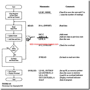
Write instructions to read incoming data from input port INPORT, count the number of readings, and add the readings. When the sum exceeds FFH, stop reading the port, store the number of readings added in memory location OUTBUF, and display 01 at the output port OUTLED to indicate the overload.
Program Description
1. This program uses two labels-READ AND OVRLOD-to specify jump memory locations. Similarly, I/O ports are shown with labels: INPORT and OUTLED. To assemble this program, these labels must be replaced by appropriate addresses.
2. Register B is used to save the sum, and register C is used to count the number of readings added.
3. Initially, registers B and C are cleared. If they are not cleared. In the first operation the sum and the count will have the residual contents of registers Band C.
4. The IN instruction reads the input port, and register C counts the number of data bytes read. The two following instructions add the data bytes and save the result in register B.
5. If the addition does not generate a carry. the READ loop is repeated. When the addition generates a carry, the microprocessor sets the CY flag to indicate an overload. The program jumps to location OVRLOD, whereby the count is saved in memory location OUTBUF, and the overload is indicated by displaying 01H at the output port.

