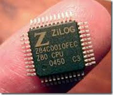
Z80 INSTRUCTIONS RELATED TO INDEX REGISTERS
The Z80 microprocessor includes two 16-bit index registers IX and IY, and they are used primarily as memory pointers. In the previous sections, we discussed instructions concerning data copy, arithmetic, and branch operations. The Z80 can perform these operations with the contents of memory registers using the index registers.
The following group shows data copy, arithmetic, and unconditional jump instructions related to the IX registers; there is an identical set for the IY register.
|
Opcode |
Operand |
Bytes |
Description |
|
LD |
IX, 16-bit |
4 |
Load 16-bit data into IX register (this instruction was discussed in Section 8.1. l) |
|
LD |
(IX + d), 8-bit |
4 |
Load 8-bit into memory location IX+ d |
|
LD |
r, (IX + d) |
3 |
Copy from memory IX + d into register r |
|
LD |
(IX+ d), r |
3 |
Copy from register r into memory IX+ d |
|
ADD |
A, (IX+ d) |
3 |
Add contents of memory IX + d to A |
|
SUB |
(IX + d) |
3 |
Subtract contents of memory IX + d from A |
|
INC |
IX |
2 |
Increment 16-bit contents of IX |
|
INC |
(IX+ d) |
3 |
Increment contents of memory IX + d |
|
DEC |
IX |
2 |
Decrement 16-bit contents of IX |
|
DEC |
(IX+ d) |
3 |
Decrement contents of memory IX+ d |
General Characteristics
1. Index registers IX and IY are used as memory pointers. The memory address is calculated by adding the displacement byte (also known as offset) to the contents of the index register. The displacement byte is an 8-bit number; it can be either positive or negative. The magnitude of a positive offset is specified by the seven bits D6-D0, and the positive sign is indicated by bit D7 being 0.
For a negative offset, the displacement byte is expressed in 2’s complement (illustrated in Example). The total offset ranges from + 127 to -128 memory locations.
2. When the operand is memory, it is specified by enclosing the memory address in the parentheses (as in any other memory-related instructions), and when the operand is the index register, it is written without parentheses.
3. The instructions listed above follow the same pattern as discussed in the previous sections.
4. These instructions have 2-byte Opcodes; therefore, the number of bytes in index-related instructions ranges from two to four bytes.
Example 8.10
Set up index registers IX and IY as memory pointers to locations 2050H and 2185H, respectively. Load data bytes 32H into location 2090H and 97H into 2120H using the index registers. Add the bytes, and save the sum in the accumulator.
Solution
|
Mnemonics |
Descriptions |
|
LD IX, 2050H |
;Point IX to location 2050H |
|
LD IY, 2185H |
;Point IY to location 2185H |
|
LD (IX + 40H), 32H |
;Load byte into location (2050H + 40H) = 2090H |
|
LD (IY + 98H), 97H |
;Load byte into location 2120H Offset is (2185H – 2120H) 65H locations backward. 2’s complement of 65H = 9BH |
|
LD A, (IX + 40H) |
;Copy first byte (32H) into A |
|
ADD A, (IY + 9BH) |
;Add second byte |
|
HALT |
The memory addresses are calculated by adding the offset to the low-order byte of the index register.
|
IX+ 40 = 20 50 +40 ————- 90H→2090H |
IY + 9B = 21 85 +9B ——- 120 Complement CY → 020 Result→ 21 20H |
Because the second operation is a 2’s complement addition, the carry is complemented.
