ILLUSTRATIVE PROGRAM 1: BLOCK TRANSFEER OF DATA BYTES
In practical applications, data transfer from one memory block to another is a common occurrence. This illustrative program demonstrates how to copy data bytes from one block of memory to another using the instructions discussed previously.
Problem Statement
Ten bytes of data are stored in a block of memory; the first location is labeled SOURCE (1850H). Transfer all data bytes to a new block starting with the location labeled OUTBUF (Output Buffer = 1870H). When the data transfer is complete, display 01 at the output port PORT0.
Problem Analysis
Ten bytes are already stored in the memory block from 1850H to 1859H (Figure). These bytes must be copied into the memory block from I870H to 1879H; these are called no overlapping memory blocks. This problem is similar to Example repeated ten times. Therefore, we must copy one byte from 1850H into
the Z80 microprocessor and then copy the byte into 1870H as shown in Figure. This process should be repeated ten times for the remaining bytes.
We can analyze this problem in terms of the generalized flowchart (Figure).
1. Initialization: In this problem, we need one counter to count ten bytes and two memory pointers: one for SOURCE memory and the other for OUTBUF memory.
2. Data Acquisition: In this problem, when a data byte is transferred from memory to the microprocessor, it is immediately transferred to a new memory location. There is no data processing; thus, we can eliminate blocks 3 and 4.
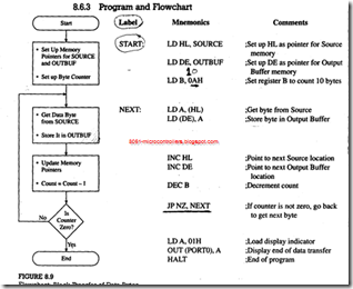
The flowchart is shown in Figure 8.9; blocks 5, 6, and 7 are identical to the blocks shown in Figure 8.7.
Program and Flowchart
Program Description and Execution
In this program, several labels are used to specify memory locations and I/O ports; this is a common industrial practice. When an assembler is used to write programs, labeling provides convenience and flexibility. In manual assembly, labels make it easy to read a program. In this problem, we need to specify or define absolute values of the labels SOURCE, OUTBUF, and PORTO, as well as the label START, the location where the program begins.
The flowchart in Figure is similar to the generalized flowchart of Figure 8.7. In the first block, registers HL and DE are used as memory pointers and register B as a counter to count ten bytes. In the next block, a byte is transferred from SOURCE memory to the accumulator using HL as the memory pointer, and the same byte is stored in OUTBUF memory using DE as the memory pointer.
The statements shown in the next block update the memory pointers and the counter. These statements may appear strange as algebraic equations; in fact, they are not algebraic statements but value assignments. The statement Count = Count – 1 means the new value is obtained by decrementing the previous value at the completion of one loop. It is important to remember that updating should be done before the decision making because once the Jump instruction finds that the Zero flag is not set, the program execution will go back to location NEXT. When the counter B is decremented to 0, the DEC B instruction sets the Zero flag. The program execution falls out of the loop and displays 01 at PORT0; this is shown as End in the flowchart.
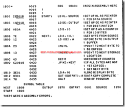
An example of the assembled program using an assembler is shown below. The assembler used is ZAD from CAMI Research, and the starting memory address is 1800H. In the following program, note that (1) instruction codes are shown on one line, (2) the memory addresses are skipped accordingly, and (3) the 16-bit numbers are entered in the reverse order, i.e., low order first, followed by high order. If you are assembling this program manually, you should ignore label definitions and assembler directives such as ORG.


