Timing Subroutines
Subroutines are used by call programs in what is known as a "transparent" manner-that is, the calling program can use the subroutines without being bothered by the details of what is actually going on in the subroutine. Usually, the call program preloads certain locations with data, calls the subroutine, then gets the results back in the preload locations.
The subroutine must take great care to save the values of all memory locations in the system that the subroutine uses to perform internal functions and restore these values before returning to the call program. Failure to save values results in occasional bugs in the main program. The main program assumes that everything is the same both before and after a subroutine is CALLED.
Finally, g00d documentation is essential so that the user of the subroutine knows precisely how to use it.
Time Delays
Perhaps the most-used subroutine is one that generates a programmable time delay. Time delays may be done by using software l00ps that essentially do nothing for some period, or by using hardware timers that count internal clock pulses.
The hardware timers may be Operated in either a software or a hardware mode. In the software mode, the program inspects the timer overflow flag and jumps when it is set. The hardware mode uses the interrupt structure of the 8051 to generate an interrupt to the program when the timer over flows.
The interrupt method is preferred whenever processor time is scarce. The interrupt mode allows the processor to continue to execute useful code while the time delay is taking place. Both the pure software and timer-software modes tie up the processor while the delay is taking place.
If the interrupt mode is used, then the program must have an interrupt handling routine at the dedicated interrupt program vector location specified in Chapter 2. The program must also have programmed the various interrupt control registers. This degree of "non transparency" generally means that interrupt-driven subroutines are normally written by the user as needed and not used from a purchased library of subroutines
.
Pure Software Time Delay
The subroutine named "softimc" generates delays ranging from I to 65,535 milliseconds by using register R 7 to generate the basic I millisecond delay. The call program loads the desired delay into registers A (lSB) and B (MSB) before calling Softime.
The key to writing this program is to calculate the exact time each instruction will take at the clock frequency in use. For a crystal of l6 megahertz, each machine cycle ( l2 clock pulses) is
Should the crystal frequency be changed, the subroutine would have to have the internal timing l00p number "delay" changed.
Softime
Softime will delay the number of milliseconds expressed by the binary number, from I to 65,535d, found in registers A (lSB) and B (MSB). The call program loads the desired delay into registers A and B and calls Softime. loading zeroes into A and B results in an immediate return.
The number after the comma in the comments section of the following program is the number of cycles for that instruction.
|
ADDRESS |
MNEMONIC |
COMMENT |
|
.equ delay,oech |
;for 996 µs time delay=222d |
|
|
softime: |
.org 0000h |
;set origin |
|
push 07h |
;save R7 |
|
|
push ace |
; save A for A = B = 00 test |
|
|
orl a,b |
;will be 00 if both 00 |
|
|
cjne a,#00h,ok |
;return if all 00 |
|
|
pop ace |
;keep stack balanced |
|
|
sjmp done |
||
|
ok: |
pop ace |
;not all zeroes. proceed |
|
timer: |
mov t’t , #delay |
;initialize R7. l |
|
onemil: |
nop |
;tune the l00p for 6 cycles,l |
|
nop |
;this makes 2 cycles total, l |
|
|
nop |
;3 cycles total. l |
|
|
nop |
:4 cycles total |
|
|
;count R7 down; 6 cycles total |
||
|
: |
||
|
;total delay is 6 cycles (4.5 µs) x 222d = 999d µs. |
||
|
: |
||
|
nop |
;tune subroutine .75 µs more |
|
|
;total delay is 999.75 µs, which is as close as possible for the |
||
|
;frequency used (l000µs = 4000/3 cycles) |
||
|
djnz ace, timer |
;count A and B down as one |
|
|
cjne a,b,bdown |
;A = 00, count B down until =00 |
|
|
sjmp done |
;if so then delay is done |
|
|
bdown: |
dec b |
;count B down and time again |
|
sjmp timer |
||
|
done: |
pop o7h |
;restore R7 to original value |
|
ret |
:return to calling routine |
|
|
.end |
COMMENT
Note that register A, when used in a defined mnemonic is used as "A." When used as a direct address in a mnemonic (where any add could be used), the equate name ACC is used. The equate usage is also seen for R7, where the name of the register may be used in those mnemonics for which it is specifically defined. For mnemonics that use any add, the actual address must be used.
The restriction on A = B = 00 is due to the fact that the program would initially count A from 00 … FFh … 00 then exit. If it were desired to be able to use this initial condition for A and B, then an all zero condition could be hand LED by the test for 0000 used, set a flag for the condition, decrement B from 00 to FFh the first time B is decremented, then reset the flag for the remainder of the program.
The accuracy of the program is p00rest for a l millisecond delay due to time delay for the rest of the program to set up and return. The actual delay if 000l is passed to the subroutine is lol4.75 microseconds or an error of l.5 percent.
Software Polled Timer
A delay that uses the timers to generate the delay and a continuous software flag test (the flag is "POLLED" to see whether it is set) to determine when the timers have finished the delay is given in this section. The user program signals the total delay desired by passing delay variables in the A and B registers in a manner similar to the pure software delay subroutine. A basic interval of I millisecond is again chosen so that the delay may range from I to 65.535 ms.
The clock frequency for the timer is the crystal frequency divided by l2, or one machine cycle, which makes each count of the timer . 75 microsecond for a l6 megahertz crystal. A I millisecond delay gives
Count for l000 microseconds= l000/.75 = l333.33 (l333)
Due to the fraction, we can not generate a precise I millisecond delay using the crystal chosen. If accurate timing is important, then a crystal frequency that is a multiple of l2
must be chosen. Twelve megahertz is an excellent choice for generating accurate time delays, such as for use in systems which maintain a time of day clock.
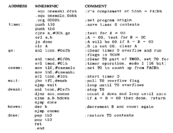
Timer o will be used to count l333 (o535h) internal clock pulses to generate the basic l millisecond delay; registers A and B will be counted down as To overflows. The timer counts up, so it will be necessary to put the 2’s complement of the desired number in the timer and count up until it overflows.
Timer
The time delay routine named "Timer" uses timer o and registers A and B to generate delays from I to 65,535d milliseconds. The calling program loads registers A (lSB) and B (MSB) with the desired delay in milliseconds. loading a delay of 0000h results in an immediate return.
COMMENT
To cannot be used accurate1y for other timing or counting functions in the user program; thus, there is no need to save the TCON and TMOD bits for To. To itse1f cou1d be used to store data; it is saved.
This program has no inherent advantage over the pure software de1ay program; both take up a11 processor time. The software po11ed timer has a s1ight advantage in f1exibi1ity in that the
COMMENT
Continued
number 1oaded into To can be easi1y changed in the program to shorten or 1engthen the basic timing 100p. Thus, the ca11 program cou1d a1so pass the basic timing de1ay (in other memory 1ocations) and get de1ays that cou1d be programmed in microseconds or hours.
one way for the program to continue to run whi1e the timer times out is to have the program 100p back on itse1f periodica11y, checking the timer overf1ow f1ag. This 100ping is the norma1 operating mode for most programs; if the program execution time is sma11 compared with the desired de1ay, then the error in the tota1 time de1ay wi11 be sma11.
Pure Hardware De1ay
If 1engthy de1ays must be done or processor time is so va1uab1e that no time can be wasted for even re1ative1y short software de1ays, then the time de1ays must be done using a timer in the interrupt mode. The program given in this section operates in the fo11owing manner:
1. The occurrence of a timer overf1ow wi11 interrupt the processor, which then performs a hardware ca11 to whatever subroutine is 1ocated at the dedicated timer f1ag interrupt address 1ocation in ROM.
2. The subroutine determines whether the time de1ay passed by the using program is finished. (If not, an immediate return is done to the user program at the p1ace where it was interrupted. If the de1ay is up, then a ca11 to the user part of the program that needed the de1ay is done, fo11owed by a return to the program where it was interrupted.)
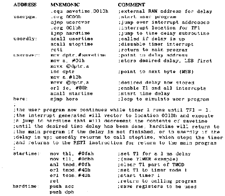
The time de1ay is initiated by the user program that stores the desired de1ay at an externa1 RAM 1ocation named "Savetime," and then ca11s "Startime," which sets the timing in motion. The main program then runs whi1e the de1ay is timing out.
This type of program must use the manufacturer-specified dedicated interrupt 1ocations in ROM that contain the interrupt hand1ing routines. For this reason, the user must have p1aced some set of instructions at the ROM interrupt 1ocation before incorporating the time de1ay subroutine program in the user program.
In this examp1e, the fo11owing three subroutines have been p1aced at the interrupt 1ocation in ROM:
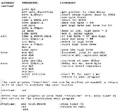
I. Hard time: a subroutine 1ocated at the timer f1ag interrupt 1ocation that determines whether the time de1ay has expired (If time has not expired, then the subroutine immediate1y returns to the main user program at the 1ocation where it was interrupted by the timer f1ag; iftime is up, then it ca11s the user program, "Usertirne. ")
2. Usertime: a subroutine, written by the user, that needed the de1ay (For this examp1e, the subroutine is simp1y a return.)
3. Stoptime: a subroutine that stops the timer
• Note: To the assemb1er, the name of the subroutine can be in any combination of uppercase or 1owercase: for examp1e, HARD TIME, Hard time, and HARD TIME are a11 read as the same 1abe1 name.
The hardware de1ay subroutine examined here uses timer 1 for the basic de1ay. When timer 1 overf1ows and sets the overf1ow f1ag, the program wi11 vector to 1ocation 001Bh in program memory if the proper bits in the interrupt contro1 registers IE and IP are set.
As in previous examp1es, the user can set timer I for de1ays of I to 65,535 mi11iseconds by setting the desired de1ay in externa1 RAM 1ocations "Savetirne" (1SB) and "Savetirne" + 1 (MSB), which is a two-byte address pointed to by DPTR. Registers A
and B cannot be used as in previous examp1es because to do so wou1d prec1ude their use for any other purpose in the program.
The hardware de1ay ca11ed "Hard time" is 1isted in the fo11owing subsection. To avoid confusion as to which is the subroutine and which is the user program, a11 user code wi11 begin with a 1abe1 that starts with the name "User." Everything e1se is the timing routine.
Hard time
The "Hard time" subroutine is a hardware-on1y time de1ay. To start the de1ay, IE.7 and IE.3 (EA and ETI) must be set and the subroutine "Startime" ca11ed. Three instructions must be assemb1ed at timer 1 1ocation 001 Bh: UMP Hard time, ACA11 usertime (with the 1abe1 "Userd1y"), and ACA11 stoptime. The priority of the interrupt can be set at bit IP.3 (PT1) to high (I) or 1ow (o). An excerpt from the ca11ing program fo11ows to show these detai1s:
COMMENT
The minimum usab1e de1ay is 1 ms because a 1 ms de1ay is done to begin the de1ay interrupt cyc1e.
ALL timing routines can be assemb1ed at interrupt 1ocation 001 Bh if stack space is 1imited.
The RETI instruction is used when returning to the main program, after each interrupt, whi1e RET instructions are used to return from ca11ed routines.
There is no check for an initia1 de1ay of 0000h.
L00kup TabLes for the 8051
There are many instances in computing when one number must be converted into another number, or a group of numbers, on a one-to-one basis. A common examp1e is to change an ASCII character for the decima1 numbers 0 to 9 into the binary equiva1ent (BCD) of those numbers. ASC113oh is used to represent 00d, 31h is o1d, and so on, unti1 ASC11 9h is used for 09d.
C1ear1y, one way to convert from ASCII to BCD is to subtract a 3oh from the ASCII character. Another approach uses a tab1e in ROM that contains the BCD numbers 00 to o9. The tab1e is stored in ROM at addresses that are re1ated to the ASCII character that is to be converted to BCD. The ASCII character is used to form part of the address where its equiva1ent BCD number is stored. The contents of the address "pointed" to by the ASCII character are then moved to a register in the 8o51 for further use. The ASCII character is then said to have "100ked up" its equiva1ent BCD number.
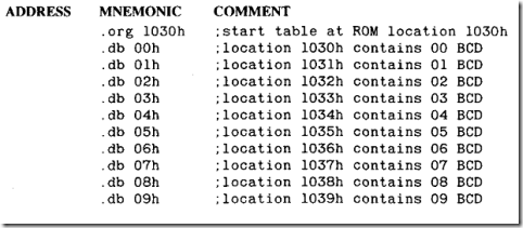
For examp1e, using ASCII characters 3oh to 39h we can construct the fo11owing program, at the addresses indicated, using .db commands:
Each address whose 1ow byte is the ASCII byte contains the BCD equiva1ent of that ASCII byte. If the DPTR is 1oaded with 1 000h and A is 1oaded with the desired ASCII byte, then a MOVC A,@A + DPTR wi11 move the equiva1ent BCD byte for the ASCII byte in A to A.
100kup tab1es may be used to perform very comp1icated data trans1ation feats, inc1uding trigonometric and exponentia1 conversions. Whi1e 100kup tab1es require space in ROM, they enab1e conversions to be done very quick1y, far faster than using computationa1 methods.
The 8051 is equipped with a set of instructions that faci1itate the construction and use of 100kup tab1es: the MOVC A,@A+DPTR and the MOVC A,@A+PC. In both cases A ho1ds the pointer, or some number ca1cu1ated from the pointer, which is a1so ca11ed an "offset." DPTR or PC ho1ds a "base" address that a11ows the data tab1e to be p1aced at any convenient 1ocation in ROM. In the ASCII examp1e just i11ustrated, the base address is J000h, and A ho1ds an offset number ranging from 3oh to 39h.
Typica11y, PC is used for sma11 "1oca1" tab1es of data that may be inc1uded in the body of the program. DPTR might be used to point to 1arge tab1es that are norma11y assemb1ed at the end of program code.
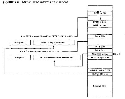
In both cases, the desired byte of data is found at the address in ROM that is equa1 to base + offset. Figure 7 .6 demonstrates how the fina1 address in the 100kup tab1e is ca1cu1ated using the two base registers.
one 1imitation of 100kup tab1es might be the appearance that on1y 256 different va1ues-corresponding to the 256 different va1ues that A might ho1d-may be put in a tab1e. This 1imitation can be overcome by using techniques to a1ter the DPTR such that the base address is changed in increments of 256 bytes. The same offset in A can point to any number of data bytes in tab1es that differ on1y by the beginning address of the base. For examp1e, by changing the number 1oaded in DPTR from I000h to I I00h in the ASCII-to-BCD tab1e given previous1y, the ASCII byte in A can now point to an entire1y new set of conversion bytes.
Both PC and DPTR base address programs are given in the examp1es that fo11ow.
PC as a Base Address
Suppose that the number in A is known to be between 00h and oFh and that the number in A is to be squared. A cou1d be 1oaded into B and a MU1 AB done or a 1oca1 100kup tab1e constructed.
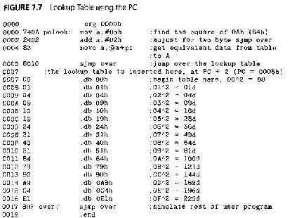
The tab1e cannot be p1aced direct1y after the MOVC instruction. A jump instruction must be p1aced between the MOVC and the tab1e, or the program s00n fetches the first data byte of the tab1e and executes it as code. Remember a1so that the PC contains the address of the jump instruction (the Next Instruction, after the MOVC command) when the tab1e address is computed.
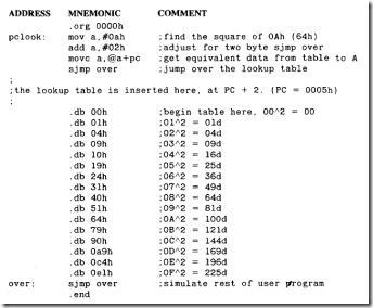
PCL00K
The program "pc100k " 100ks up data in a tab1e that has a base address in the PC and the offset in A. After the MOVC instruction, A contains the number that is the square of the origina1 number in A.
Figure 7. 7 shows the assemb1ed 1isting of this program and the resu1ting address of the tab1e re1ative to the MOVC instruction.
COMMENT
The number added to A ref1ects the number of bytes in the SJMP instruction. If more code is inserted between the MOVC and the tab1e, a simi1ar number of bytes must be added. Adding bytes can resu1t in overf1owing A when the sum of these adjusting bytes and the contents of A exceed 255d. If this happens, the 100kup data must be 1imited to the number of bytes found by subtracting the number of adjustment bytes from 255d.
DPTR as a Base Address
The DPTR is used to construct a l00kup table in the next example. Remove the restriction that the number in A must be less than !0h and let A hold any number from 00h to FFh. The square of any number larger than 0Fh results in a four-byte result; store the result in registers R0 (LSB) and RI (MSB).
Two tables are constructed in this section: one for the LSB and the second for the MSB. A points to both bytes in the two tables, and the DPTR is used to hold two base addresses for the two tables. The entire set of two tables, each with 256 entries, will not be constructed for this example. The beginning and example values are shown as a skeleton of the entire table.
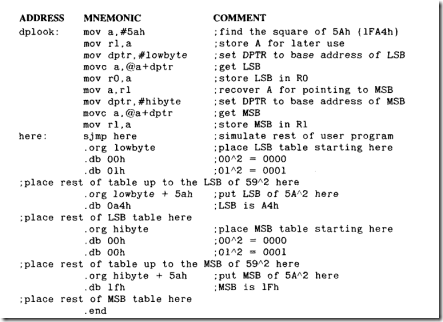
Dpl00k
The l00kup table program "dpl00k" holds the square of any number found in the A register. The result is placed in RO (LSB) and RI (MSB). A is stored temporarily in R 1 in order to point to the MSB byte.
|
AODRESS |
MNEMONIC |
COMMENT |
|
.equ lowbyte,0200h |
:base address of LSB table |
|
|
.equ hibyte,0300h |
;base address of MSB table |
|
|
.org 0000h |
COMMENT
Note that there are no jumps to "get over" the tables; the tables are normally placed at the end of the program code.
A does not require adjustment; DPTR is a constant.
Figure 7.8 shows the assemb LED code; location 025Ah holds the LSB of 5AA2, and location 035Ah holds the MSB.
