Putting it all Together
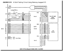
All of the examples presented to this point have used the free ports (Pl and parts of P3) that the "cheap" design affords. It is clear that to do a real-world design requires the use of additional port chips to enable several functions to be interfaced to the 805 l at one time. Such a design is illustrated in this section, using an 8255 programmable port chip memory mapped at external RAM location 8000h to 8003h. A review of memory mapping found in Chapter 7 shows that the required address decoding can be done using an inverter to enable external RAM whenever Al5 is low, and the 8255 whenever Al5 is high. Actually, any address that begins with Al5 high can address the 8255; 8000h seems convenient.
Ant
The example program uses the intelligent LCD display, a coded 16-key keypad, and is capable of serial data communications. This type of design is suitable for many applications where a small, inexpensive, alphanumeric terminal (dubbed the ANT) is needed for the factory fl00r or the student lab.
The design is shown in Figure 8.14. Port A of the 8255 is connected to the keypad.
Port B supplies data bytes to the LCD and the lower half of port C controls the display. The program is interrupt driven by the keypad and the serial port. I͞N͞T͞0 is used to detect a keypress via the AND gate array while the serial interrupt is internal to the 8051. The serial port has the highest priority. This type of program is often called "multi-tasking" because the routines are called by the interrupt structure, and the computer appears to be doing many things simultaneously.
A keypad program developed in this chapter combined with a serial communication program from Chapter 9 completes the design.
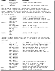
The program "Ant" controls the actions of an 8051 configured as a terminal with a LCD display and hexadecimal keypad. The serial port is enabled, and has the highest priority of any function. The coded keyboard is a two-of-eight type which can use a lookup table to detect valid key presses. A shift key capability is possible because unique patterns are possible if one key is held down while another is pressed.
COMMENT
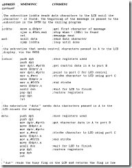
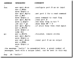
The LCD example shows the extensive use of the DPTR and MOVX command when dealing with a memory mapped external port.
Forgetting to terminate every message with a – results in a very confused LCD as the remainder of roM is written to the LCD.
There will be no interference between any of these programs if the serial interrupts always have priority. Serial data is received as it occurs, and the keypad program and any messages to the LCD are suspended for the few microseconds it takes to read the serial port. The suspended programs can resume until the next serial character. which is normally an interval of one or more milliseconds.
Summary OF 8051 Applications
Hardware designs and programs have been illustrated to solve several common application problems that are especially suitable for solution using a microcontroller. These hardware circuits are
Keyboards: Lead-per-key, X-Y matrix, coded
Displays: 7-segment LED, intelligent LCD
Pulse measurement: frequency, pulse width
Data converters: Rl2R digital to analog, flash analog to digital
Interrupts: multi-source, daisy chain
Expanded 8051 system: memory-mapped I/O
The programs in this chapter interface the 8051 to these circuits. New programming concepts introduced are
Interrupt handling
Register bank switching in "Svnseg"
Jump tables in "Lopri "
Stack RETI in "Hipri"
Using CJNE for relative size in "Hardin!"
Multitasking in "Ant"
These programs can he used as the kernels for more comprehensive applications.
Problems
1. List the most likely effects if a keyboard program does not accomplish the following:
a. Debounce keys when pressed down
b. Check for a valid key code
c. Wait for all keys up before ending keyboard routine
d. Debounce keys when released
2. A keyboard has two keys: run and stop. Write a program that is interrupt driven by these two keys using I͞N͞T͞0 for the run key. and INTI for the stop key. If run is selected. set pin P3.0 high; if stop is selected. set the pin low. Bounce time is io milliseconds for
the keys.
3. Determine why it is important to employ some kind of debounce subroutine in a keyboard program, particularly for interrupt driven programs. even if keys with absolutely no bounce are used.
4. The lookup table used in the program "Codekey" is very inefficient. using 256 bytes to form a table for the valid keys and using an FFh in all other locations for invalid keys. Write a subroutine using a series of CJNE instructions that will obtain the same result.
5. Repeat problem 4 by converting the keycode number in A from the codes B7h-EEh to 00-09h. One way to do this is to convert the first and second nibbles to the following numbers and then adding the nibbles to get a unique number:
Note: Lookup tables can be used for each conversion, with invalid codes in both nibble lookup tables set to return numbers that, when added, sum to greater than 09.
6. Write a lookup table subroutine for the program "Bigkey " that will convert the row and column bytes for each key to a single byte number.
7. Expand the lookup table "convert" in the program "Svnseg" to include these characters:
G, H. I, J, L. O, P, S. T, and U.
8. Write a program that will display the following message on the intelligent display:
"Hello!
Please Enter Command."
Center each line of the display.
9. Write a subroutine that is past the starting address of an ASCII string in roM and then displays the string on the intelligent display. The string length is fixed.
io. Repeat Problem 9 for a string of any length.
11. Write a program for the LCD display that will display the contents of register RI as follows:
Rl =XX
XX is the R1 contents in hex. Center the display. (Hint: Remember the contents arc in hex, and the display speaks ASC11.)
12. Write a program using timer 0 that will delay exactly . io0000 milliseconds ± 1 microsecond from the time the timer starts until it is stopped. (The crystal frequency is 16 megahertz).
13. Make a table that shows the accuracy of pulse width measurements as a function of multiples of count periods (. 75 microseconds). The table should be arranged as follows:
|
PULSE WIDTH (x.75 µs) 2 |
ACCURACY(%) 1 |
|
3 4 5 6 7 8 9 |
|
|
io |
|
|
20 |
|
|
50 |
|
|
io0 |
14. Write a program that can use the stack to "return" to any of 256 subroutines pointed to by the number 00 to FFh in A.
15. Compose a 40-value lookup table that will generate a sawtooth wave using a D/ A converter.
16. Repeat Problem 15 without using a lookup table of any kind.
17. Repeat Problem 15 for a rectified sine wave.
18. Outline a method of measuring the frequency of a sine wave using a flash A/D converter. Estimate the highest frequency that can he measured to an accuracy of I percent.
19. In the section on measuring frequency. an expression was found for n bit resolution of a frequency measured over time, T:
Derive an equivalent expression for the resolution of a frequency to n bits by measuring the period of M of the cycles.
20. ‘Write a program that finds frequency by measuring the time for M cycles of the unknown periodic wave. Estimate the highest frequency that can be measured to an accuracy of
1 percent if the crystal is 16 megahertz.
21. Write a program that performs all of the functions of an intelligent daisy chain interrupt source controller.
22. Write a lookup table program for the "Ant" program that will allow the F key of a two-of-eight coded keypad to be used as a shift key. A shift key makes possible 31 valid key combinations. The key codes are


