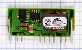
Often referred to as a switching regulator, and sometimes as a switcher, not to be confused with a switching power supply.
What It Does
A DC-DC converter, often referred to simply as a converter, receives a DC voltage as its input and converts it to a regulated DC voltage as its out put. The output voltage may be higher or lower than the input voltage, may be user-adjustable by adding an external resistor, and may be completely electrically isolated from the input, de pending on the type of converter that is used.
There is no single symbol to represent a DC-DC converter. Some simplified schematics showing the principles of operation of commonly used converters are referenced under the following Variants section.
A DC-DC converter is also typically found in the output stage of a switching AC-DC power sup ply.
The overall efficiency is not greatly affected by
the difference between input and output volt age, and can exceed 90%, minimizing waste heat and enabling the unit to be extremely compact.
A DC-DC converter is an integrated circuit pack age that includes a high-speed switching device (almost always, a MOSFET) in conjunction with an oscillator circuit, an inductor, and a diode. By comparison, a linear regulator is usually based around bipolar transistors. Its input must always be at a higher voltage than its output, and its efficiency will be inversely proportional with the voltage drop that it imposes. See the voltage regulator entry in this encyclopedia for additional information.
How It Works
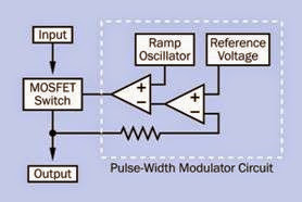
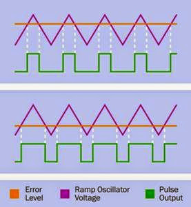
An internal oscillator controls a MOSFET semi conductor that switches the DC input on and off at a high frequency, usually from 50KHz to 1MHz. Output voltage is adjusted by varying the duty cycle of the oscillator—the length of each “on” pulse relative to each “off” interval. This is known as pulse-width modulation, or PWM. The duty cycle is controlled by sampling the output of the converter and using a comparator to subtract the output voltage from a reference voltage, to establish an error value. This is passed to another comparator, which subtracts the error voltage from an oscillator ramp signal. If the error increases, the oscillator signal is more heavily clipped, thus changing the effective ratio of on/off pulse
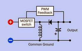
lengths. A simplified schematic of the PWM circuit is shown in Figure 17-1, which omits other components for clarity. The system of subtracting an error voltage from a ramp oscillator volt age to obtain a pulse-width modulated signal is illustrated in Figure 17-2.
Figure 17-1. The heart of a DC-DC converter is a MOSFET switch, which operates at a high frequency with pulse-width modulation used to create an adjustable DC output.
Figure 17-2. To achieve pulse-width modulation, an error- level voltage is established by comparing the output from the converter with a reference voltage. The error level, shown as an orange line, is then subtracted from the out- put from a ramp oscillator. The pulse width varies accordingly.
The key to the efficiency of a DC-DC converter is an inductor, which stores energy in its magnetic field during “on” pulse and releases it in the dis charge phase. Thus, the inductor is used as a temporary reservoir and minimizes the ripple current. All converter variants use a coil for this purpose, although its placement varies in relation to the diode and capacitor that complete the basic circuit.
Variants
Four basic switching circuits are used in DC-DC converters and are defined in the coming sections, with a formula to determine the ratio be tween input voltage (Vin) and output voltage (Vout) in each case. In these formulae, variable D is the duty cycle in the pulse train generated through an internal MOSFET switch. The duty cycle is the fraction of the total on-off cycle that is occupied by each “on” pulse. In other words, if
Ton is the duration of an “on” pulse and Toff is the “off” time:
0= Ton / (Ton + Toff)
Buck Converter
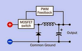
See Figure 17-3. The output voltage is lower than the input voltage. The input and output share a common ground. For this circuit:
Vout = Vin * D
Figure 17-3. Basic topology of a buck-type DC-DC converter.
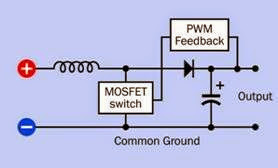
See Figure 17-4. The output voltage is greater than the input voltage. The input and output share a common ground. For this circuit:
Vout = Vin / (1-D)
Figure 17-4. Basic topology of a boost-type DC-DC converter.
Flyback Converter with Inductor
Commonly known as a buck-boost converter. See Figure 17-5. The output voltage can be less than or greater than the input voltage. The input and
output share a common ground. For this circuit:
Figure 17-5. Basic topology of a fly back type DC-DC converter.
Fly back Converter with Transformer
See Figure 17-6. The output voltage can be less than or greater than the input voltage. The input and output are isolated from one another. For this circuit:
Vout = Vin * (D / (1-D))
Figure 17-6. Basic topology of a fly back type DC-DC con- verter. (Buck, boost, and fly back topologies adapted from Maxim Integrated Products.)
Using a transformer in the converter allows multiple outputs with different voltages, supplied through multiple transformer windings.
Formats
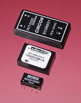
A converter may be packaged in a flat rectangular box that requires no additional heat sink and has pins for through-hole insertion into a PC board. Sizes usually range up to to 2” × 2”. Power handling can range from 5 to 30 watts. Converters of this type are shown in Figure 17-7. (Top: Input range of 9 to 18VDC, fixed output of 5VDC at 3A completely isolated from the input. Typical efficiency of approximately 80%. The case is made of copper, providing good heat dissipation with electrical shielding. Center: Input range of 9 to 18VDC, fixed output of 5VDC at 500mA completely isolated from the input. Typical efficiency of approximately 75%. The manufacturer claims that external capacitors are only needed in critical applications. Bottom: SIP format, fixed input
of 12VDC, fixed output of 5VDC at 600mA completely isolated from the input. Typical efficiency of approximately 75%. Requires external capacitors for ripple rejection.)
Figure 17-7. A selection of sealed DC-DC converters.
Lower-power converters are also available as surface-mount devices.
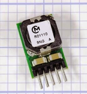
Some adjustable-output converters are supplied as multiple surface-mounted components pre installed on a mini-board that has pins for through-hole insertion in a printed circuit board. Their high efficiency enables them to handle a lot of power for their size. In Figure 17-8, the converter accepts a 4.5 to 14VDC input range and has an adjustable output of 0.6 to 6VDC. It is rated at a surprising 10A or 50W and is more than 90% efficient. However, it draws 80mA in a no-load state, causing it to become quite hot. A thermal cutout or automatic shutdown may be used if the converter will not be driving a consistent load.
Figure 17-8. An adjustable DC-DC converter rated for 10A or 50W. The output voltage is determined by adding an external resistor or trimmer potentiometer. External smoothing capacitors are required, as shown in the component’s datasheet.
The miniboard in Figure 17-9 accepts an input voltage from 7 to 36VDC and has an adjustable output ranging from 2.5 to 12.6VDC, at up to 6A. It is non-isolated (has a common negative bus) and claims to be more than 95% efficient at full load.
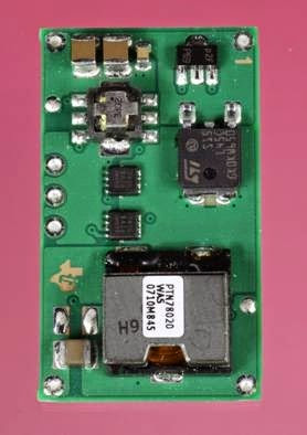
The miniboard in Figure 17-10 accepts an input voltage from 4.5 to 14VDC and has an adjustable output ranging from 0.6 to 6VDC at up to 20A. It is non-isolated (has a common negative bus) and claims to be more than 90% efficient at full load.
Values
Relevant values include:
Nominal Input Voltage and Frequency
A wide range of input voltages is often acceptable, as the PWM can vary accordingly. Converters
Figure 17-9. Another adjustable DC-DC converter. The output voltage is determined by adding an external resistor or trimmer potentiometer. External smoothing capaci- tors are required, as shown in the component’s datasheet.
Figure 17-10. Another adjustable DC-DC converter. The output voltage is determined by adding an external resistor or trimmer potentiometer. External smoothing capaci- tors are required, as shown in the component’s datasheet.
often allow equipment to be usable internation ally, on any voltage ranging from 100VAC to 250VAC, at a fequency of 50Hz or 60Hz, without any adaptation.
Output Voltage
As previously noted, many converters allow the output voltage to be adjusted by adding an external resistor or potentiometer. Alternatively, there may be multiple fixed output voltages, ac cessible via different pins on the package. They may also provide a positive voltage and equally opposite negative voltage relative to a ground pin.
Input Current and Output Current Because input voltage and output voltage are likely to be different, the current alone is not a reliable guide to power handling.
A datasheet should specify input current with no load (open circuit on the output side). This cur rent will have to be entirely dissipated as heat.
Load Regulation
This is usually expressed as a percentage and suggests the extent to which output voltage may be pulled down when the load on a DC-DC converter increases. If Vnil is the measured output voltage with no load, and Vmax is the measured output voltage with the maximum rated load:
Load regulation = 100 * (Vnil – Vmax)/Vmax
However, note that some converters are de signed with the expectation that they will never be used with zero load across the output. In these cases, Vnil will be the voltage at minimum rated load.
Efficiency
This is a measure of how much input current must be dissipated as heat. A converter with a 12-volt input, drawing a maximum 300mA input current, will consume 3.6 watts (3,600mW). If it is 80% efficient, it will have to dissipate roughly 20% of its power as heat, or 720mW.
Sometimes abbreviated R/N, this may be measured in mV or as a percentage. Check the specification carefully to determine whether the ripple-and-noise values require use of external smoothing capacitors. Often, this is the case.
Isolated or Non-Isolated
This crucial piece of information is often found near the top of a datasheet, not in the detailed specifications.
How to Use it
Because a converter creates electrical noise, it should be prevented from affecting other com ponents by adding substantial bypass capacitors as close as possible to its input and output pins. For most converters, external capacitors are mandatory, and their effective series resistance (ESR) should be as low as possible (see the capacitor entry in this encyclopedia for an explanation of ESR). Tantalum capacitors are preferable to electrolytics for this reason, and are also more durable. Some manufacturers recommend placing a tantalum capacitor in parallel with an electrolytic. A small ceramic capacitor, typically 0.1μF, is often recommended in an addition to larger- value capacitors on the output side.
The voltage rating of each capacitor should be twice the voltage at the point in the circuit where it is used. The capacitance value will usually be higher for higher-current converters. Values of 100μF are common, but for high amperage, a value may be as high as 1,000μF.
While datasheets are often inadequate for some types of components, datasheets for DC-DC converters usually include detailed instructions regarding bypass capacitors. Following these in structions is essential. In the relatively rare in stances that a datasheet makes no mention of bypass capacitors for a converter, this does not necessarily mean that the capacitors are unnec essary. The manufacturer may assume that they will be used as a matter of course.
Converters are used in a very wide range of de vices, supplying power ranging from a few milli amps to tens of amps. At the lower end of the scale, devices such as cellular telephones, portable computers, and tablets contain sub- circuits that require different voltages, some of which may be higher than the voltage of a single battery or battery pack that powers the device. A converter can satisfy this requirement. Because a converter can be designed to maintain a fixed output in response to a range of input voltages, it can also compensate for the gradual decline in voltage that occurs during battery usage.
A boost-type converter can be used to double the voltage from a single 1.5V battery in an LED flashlight where 3 volts are required to power the LED. Similarly, a boost-type converter can pro vide the necessary voltage to run a cold-cathode fluorescent tube that provides backlighting in an LCD computer display.
On a circuit board that is primarily populated with 5VDC components and is fed by a single 5VDC power supply, a converter can be used to supply 12VDC for one special purpose, such as an analog-digital converter or a serial data connection.
If electromechanical relays or other inductive loads share a common ground with components ,such as logic chips or microcontrollers, it may be difficult to protect the sensitive compo nents from voltage spikes. A A fly back converter with a transformer separating the output from the input can allow the “noisy” section of the circuit to be segregated, so long as the converter itself does not introduce noise. Since the electromagnetic interference (EMI) introduced by converters varies widely from one model to an other, specifications should be checked carefully.
Very low-power components can pick up EMI from the wires or traces leading into and out of a converter. In this type of circuit, adequate noise suppression may be impossible, and a converter may not be appropriate.
Electrical Noise in Output
Electrolytic capacitors may be inadequate to smooth the high frequencies used. Multilayer ceramic capacitors or tantalum capacitors may be necessary. Check the manufacturer’s datasheet for minimum and maximum values. Also check the datasheet for advice regarding placement of capacitors on the input side as well as across the output.
Excess Heat with No Load
Some converters generate substantial heat while they are powered without a load. The manufacturer’s datasheet may not discuss this potential problem very prominently or in any detail. Check the input rating, usually expressed in mA, speci fied for a no-load condition. All of this current will
have to be dissipated as heat, and the very small size of many converters can result in high localized temperatures, especially since many of them allow no provision for a heat sink.
Inaccurate Voltage Output with Low Load
Some converters are designed to operate with at least 10% of full rated load across their output at all times. Below this threshold, output voltage can be grossly inaccurate. Read datasheets care fully for statements such as this: “Lower than 10% loading will result in an increase in output volt age, which may rise to typically double the specified output voltage if the output load falls to less than 5%.” Always use a meter to verify the output voltage from a converter at a variety of different loads, and perform this test before installing the converter in a circuit.
