EXPANDING THE INTERRUPT STRUCTURE
This text covers three of the more common methods of expanding the interrupt structure of the microprocessor. In this section, we explain how, with software and some hardware modification of the circuit shown in Figure 12–10, it is possible to expand the INTR input so that it accepts seven interrupt inputs. We also explain how to “daisy-chain” interrupts by software polling. In the next section, we describe a third technique in which up to 63 interrupting inputs can be added by means of the 8259A programmable interrupt controller.
Using the 74ALS244 to Expand Interrupts
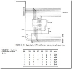
The modification shown in Figure 12–13 allows the circuit of Figure 12–10 to accommodate up to seven additional interrupt inputs. The only hardware change is the addition of an eight-input NAND gate, which provides the INTR signal to the microprocessor when any of the IR inputs becomes active.
Operation. If any of the IR inputs becomes a logic 0, then the output of the NAND gate goes to a logic 1 and requests an interrupt through the INTR input. The interrupt vector that is fetched during the INTA pulse depends on which interrupt request line becomes active. Table 12–1 shows the interrupt vectors used by a single interrupt request input.
If two or more interrupt request inputs are simultaneously active, a new interrupt vector is generated. For example, if IR1 and IR0 are both active, the interrupt vector generated is FCH (252). Priority is resolved at this location. If the IR0 input is to have the higher priority, the vector address for IR0 is stored at vector location FCH. The entire top half of the vector table and its 128 interrupt vectors must be used to accommodate all possible conditions of these seven interrupt request inputs. This seems wasteful, but in many dedicated applications it is a cost-effective approach to interrupt expansion.
Daisy-Chained Interrupt
Expansion by means of a daisy-chained interrupt is in many ways better than using the 74ALS244 because it requires only one interrupt vector. The task of determining priority is left to the interrupt service procedure. Setting priority for a daisy-chain does require additional soft- ware execution time, but in general this is a much better approach to expanding the interrupt structure of the microprocessor.
Figure 12–14 illustrates a set of two 82C55 peripheral interfaces with their four INTR out- puts daisy-chained and connected to the single INTR input of the microprocessor. If any interrupt output becomes a logic 1, so does the INTR input to the microprocessor causing an interrupt.
When a daisy-chain is used to request an interrupt, it is better to pull the data bus connections (D0–D7) high by using pull-up resistors so interrupt vector FFH is used for the chain. Any
interrupt vector can be used to respond to a daisy-chain. In the circuit, any of the four INTR out- puts from the two 82C55s will cause the INTR pin on the microprocessor to go high, requesting an interrupt.
When the INTR pin does go high with a daisy-chain, the hardware gives no direct indication as to which 82C55 or which INTR output caused the interrupt. The task of locating which INTR output became active is up to the interrupt service procedure, which must poll the 82C55s to determine which output caused the interrupt.
Example 12–7 illustrates the interrupt service procedure that responds to the daisy-chain interrupt request. The procedure polls each 82C55 and each INTR output to decide which interrupt service procedure to utilize.


