The Universal Serial Bus (USB) is one of the most common interfaces used in electronic consumer products today, including PCs, cameras, GPS devices, MP3 players, modems, printers, and scanners, to name a few.
The USB was originally developed by Compaq, Microsoft, Intel, and NEC, and later by Hewlett-Packard, Lucent, and Philips as well. These companies eventually formed the nonprofit corporation USB Implementers Forum Inc. to organize the development and publication of USB specifications.
This chapter describes the basic principles of the USB bus and shows how to use USB-based applications with PIC microcontrollers. The USB bus is a complex protocol. A complete discussion of its design and use is beyond the scope of this chapter. Only the basic principles, enough to be able to use the USB bus, are outlined here. On the other hand, the functions offered by the mikroC language that simplify the design of USB-based microcontroller projects are described in some detail.
The USB is a high-speed serial interface that can also provide power to devices connected to it. A USB bus supports up to 127 devices (limited by the 7-bit address field—note that address 0 is not used as it has a special purpose) connected through a four-wire serial cable of up to three or even five meters in length. Many USB devices can be connected to the same bus with hubs, which can have 4, 8, or even 16 ports.
A device can be plugged into a hub which is plugged into another hub, and so on. The maximum number of tiers permitted is six. According to the specification, the maximum distance of a device from its host is about thirty meters, accomplished by using five hubs. For longer-distance bus communications, other methods such as use of Ethernet are recommended.
The USB bus specification comes in two versions: the earlier version, USB1.1, supports 11Mbps, while the new version, USB 2.0, supports up to 480Mbps. The USB specification defines three data speeds:
• Low speed—1.5Mb/sec
• Full speed—12Mb/sec
• High speed— 480Mb/sec
The maximum power available to an external device is limited to about 100mA at 5.0V.
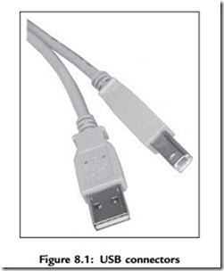
USB is a four-wire interface implemented using a four-core shielded cable. Two types of connectors are specified and used: Type A and Type B. Figure 8.1 shows typical USB connectors. Figure 8.2 shows the pin-out of the USB connectors.
The signal wire colors are specified. The pins and wire colors of a Type A or Type B connector are given in Table 8.1.
The specification also defines a mini-B connector, mainly used in smaller portable electronic devices such as cameras and other handheld devices. This connector has a fifth pin called ID, though this pin is not used. The pin assignment and wire colors of a mini-B connector are given in Table 8.2.
Two of the pins, Dataþ and Data-, form a twisted pair and carry differential data signals and some single-ended data states.
USB signals are bi-phase, and signals are sent from the host computer using the NRZI (non-return to zero inverted) data encoding technique. In this technique, the signal level is inverted for each change to a logic 0. The signal level for a logic 1 is not changed. A 0 bit is “stuffed” after every six consecutive ones in the data stream to make the data dynamic (this is called bit stuffing because the extra bit lengthens the data stream). Figure 8.3 shows how the NRZI is implemented.
A packet of data transmitted by the host is sent to every device connected to the bus, traveling downward through the chain of hubs. All the devices receive the signal, but only one of them, the addressed one, accepts the data. Conversely, only one device at any time can transmit to the host, and the data travels upward through the chain of hubs until it reaches the host.
USB devices attached to the bus may be full-custom devices, requiring a full-custom device driver, or they may belong to a device class. Device classes enable the same device driver to be used for several devices having similar functionalities. For example, a printer device has the device class 0x07, and most printers use drivers of this type.
The most common device classes are given in Table 8.3. The USB human interface device (HID) class is of particular interest, as it is used in the projects in this chapter.
Some common USB terms are:
Endpoint: An endpoint is either a source or a sink of data. A single USB device can have a number of endpoints, the limit being sixteen IN and sixteen OUT endpoints.
Transaction: A transaction is a transfer of data on the bus.
Pipe: A pipe is a logical data connection between the host and an endpoint.
Speed Identification on the Bus
At the device end of the bus, a 1.5K pull-up resistor is connected from the Dþ or D- line to 3.3V. On a full-speed bus, the resistor is connected from the Dþ line to 3.3V, and on a low-speed bus the resistor is from D- line to 3.3V. When no device is plugged in, the host will see both data lines as low. Connecting a device to the bus will pull either the Dþ or the D- line to logic high, and the host will know that a device is plugged into the bus. The speed of the device is determined by observing which line is pulled high.


