Program Analysis
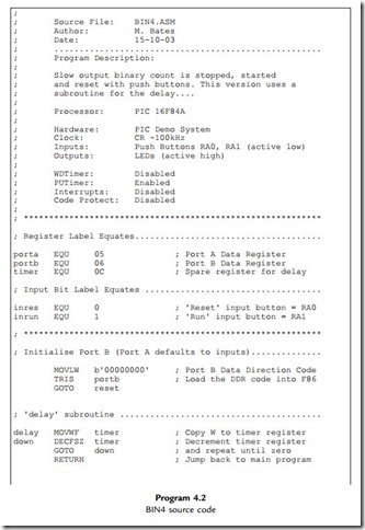
The program BIN4 will now be analyzed in some detail as it was designed to contain examples of common PIC syntax. A sample instruction of each type will be examined.
The use of labels in place of numbers makes programs easier to write and understand, but we have to ‘declare’ those labels at the beginning of the program. In assembly code, the
assembler directive EQU is used to assign a label to a number, which can be a literal, a file register number or an individual register bit. In BIN4, ‘porta’ and ‘portb’ are the port data registers (05 and 06) and ‘timer’ is the first spare register (0C), which will be used as a counter register. The labels ‘inres’ and ‘inrun’ will represent bit 0 and bit 1 of port A; they are simply given the numerical values 0 and 1. The label is replaced by the number when the program is assembled.
Port Initialization
TRIS portb
Port B is used as the output for the 8-bit binary count. The data direction must be set up using the TRIS command, which loads the port data direction register with the data direction code. In this example, the code is given in binary, b‘00000000’. This is useful, especially if the port bits are to be set as a mixture of inputs and outputs; the binary code identifies the data direction for each bit individually. This code is loaded into W using MOVLW, and the TRIS command follows.
The TRIS instruction is still available as a simple way of initializing the ports, but the manufacturers recommend an alternative method, which involves bank selection, and will be covered later. Hopefully, TRIS will continue to be supported in by the MPASM assembler, as it is easier for beginners.
Program Jumps
GOTO start
The ‘GOTO label’ command is used to make the program jump to a line other than the one following. In BIN4, ‘GOTO reset’ skips over the following DELAY routine, to start the main loop. We will come back to the reason for this in a moment. There is another unconditional jump at the end of the program, ‘GOTO start’, which makes the main loop repeat endlessly. Other ‘GOTO label’ instructions are used with ‘Test and Skip’ instructions to create conditional branches. In this program, the input buttons are checked using this type of instruction and the program branches, or not, depending on whether a button has been pressed.
Bit Test and Skip if Set/Clear
BTFSS porta,inres
The input button connected to port A, bit 0 is tested using the above instruction, which means ‘Bit Test File (register bit) and Skip the next instruction if it is Set (¼1)’. Without labels, the instruction ‘BTFSS 05,0’ would have the same effect. The buttons are connected ‘active low’, meaning that the input goes from ‘1’ to ‘0’ when the button is pressed. If the button connected to RA0 is not pressed, the input will be high, that is, set. The following instruction, ‘GOTO reset’ will therefore be skipped, and the next executed. When the button is pressed, the ‘GOTO reset’ is executed, and the CLRF instruction repeated, clearing the previous count.
BTFSC means ‘Bit Test and Skip if Clear’; it works in the same way as BTFSS, except that the logic is reversed. Thus, ‘BTFSC porta,inrun’ tests bit 1 of port A register and skips the following ‘GOTO start’ if the ‘run’ button has been pressed. The program will then proceed to increment the output count. If the button is not pressed, the program
waits by jumping back to the ‘start’ line. The combined effect of the input buttons is that the count runs when the ‘run’ button is pressed, and the count is reset to zero if the ‘reset’ button is pressed.
Decrement/Increment Register and Skip If Zero
DECFSZ timer
The other instructions for conditional branching allow a register to be incremented or decremented and then checked for a zero result, all in one instruction. This is a common requirement for counting and timing applications, and in the delay routine in BIN3, a register ‘timer’ is loaded with the maximum value FF and decremented. If the result is not yet zero, the jump ‘GOTO down’ is executed. When the register reaches zero, the GOTO is skipped and the subroutine ends. In BIN4, the timer value is set up before the delay subroutine is called.
Subroutine Call and Return
The main elements of the subroutine call structure are shown below:
In this program, the subroutine provides a delay by loading a register and counting down to zero. The delay is started using the ‘CALL delay’ instruction, when the program jumps to the label ‘delay’ and runs from there. CALL means ‘jump and come back to the same place later’, so the return address has to be stored for later recall in a special memory block called the ‘stack’.
The address of the instruction following (in this case ‘GOTO start’) is saved automatically on the stack as part of the execution of the CALL instruction. The subroutine is terminated with the instruction ‘RETURN’, which does not require an operand because the return destination address is automatically pulled from the stack and replaced in the program counter. This takes the program back to the original place in the main program. The PIC 16 stack can store up to eight return addresses, so multiple levels of subroutine can be used. The return addresses are pushed onto and pulled from the stack in order, so if a CALL or RETURN is missed out of the program, a stack error will occur. Unfortunately, this mistake will not be detected by the assembler, but will cause a run-time error message.
End of Source Code
END
The source code must be terminated with assembler directive END so that the assembly process can be stopped in an orderly way, and control returned to the host operating system. It is the only assembler directive that is essential.


