Motor Control Modules
Some examples of more complete designs for position controllers are described below.
Serial Input Position Controller
A position controller with serial input is described in Microchip® application note AN532 (Figure 11.8a). Although based on a now obsolete MCU, it represents a commercially viable design which could be updated for applications such as printers and X,Y (two-dimensional)
positioning systems. It incorporates a dc motor with quadrature (two-phase) encoder, integrated circuit full bridge driver and separate programmable logic device (PLD) encoder interface. The position demand input is received via an RS232 serial input from a master controller or PC, producing a trapezoidal output speed profile. The application note, which has some useful additional information about servo control design, can be found at www.microchip.com.
Microchip Mechatronics Kit
A very useful motor demo system is provided in the PIC Mechatronics Development Kit (Figure 11.8b). It has a dc brushed motor with a single slot wheel and a stepper motor, a reconfigurable full bridge driver and control logic. It is based on the PIC16F917, which has a dedicated interface to operate a 3.5-digit liquid crystal display (LCD). The board has a six-pin connector for PICkit2/3 programming and in-circuit debugging, and can be used as target hardware to test the programs (suitably adapted) in this chapter. For a fuller description, see the product information sheets or Programming 8-bit PIC Microcontrollers in C with Interactive Hardware Simulation by this author (Newnes 2008). A simulation schematic can be downloaded from www.picmicros.org.uk.
Recently, much attention has been directed towards brushless dc motors, which, as the name implies, eliminate the traditional commutator by using a permanent magnet rotor surrounded by a stationary set of windings. A rotating magnetic field drives the rotor, in a similar way to stepper motors. They are more efficient and reliable than brushed dc motors, but are more complex to control, requiring a three-phase full bridge driver with six transistors. Search for BLDC (Brushless DC Motor) among the Microchip Application Notes archive for background theory and demonstration circuits.
Hobby Servo
A popular position controller is the hobby servo, as used in remote-controlled systems such as model boats and planes, mainly for steering control. A compact self-contained unit contains a small dc motor, feedback pot and control chip, which receives a standard PWM signal and moves the output shaft to a position determined by the pulse width. The signal is received via a radio link to a radio-frequency receiver module, into which the control servos are plugged. The transmitter is housed in a control console with two joysticks, which can operate up to four servos, each controlling a left/right and an up/down pot.
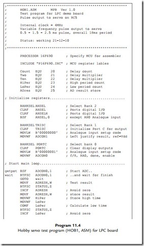
The same servo module can be connected directly to a PIC chip to provide a simple position control system. Figure 11.9 shows it connected to the LPC board for testing, as per the schematic in Figure 11.10, using program HOB1 (Program 11.4). The servo PWM input requires a TTL (transistoretransistor logic) positive pulse of between about 0.5 and 2.5 ms
(depending on the servo specification), corresponding to the limits of travel, with the mid- position set by a pulse of about 1.5 ms. Some live calibration is normally required. The overall signal period is about 18 ms, but this is not critical.
In the test circuit, the PIC reads the pot input and sets the output pulse width accordingly, so the position of the servo follows the pot. To keep it simple, software loops are used to generate the PWM, but hardware timers and interrupts will typically be used in a more complete application.
1. Outline a method of controlling the speed of a small dc motor by PWM. Identify the main hardware components required. (4)
2. Explain how an incremental encoder can be used to provide speed and position feedback from a shaft to a microcontroller. (4)
3. Based on your answers to Questions 1 and 2, explain how the speed of a dc motor can be accurately controlled by a microcontroller using digital feedback. (4)
4. (a) Calculate the positional resolution (smallest step size) in degrees at the output shaft of a robot arm drive with a 90:1 gearbox, if a shaft encoder with 200 steps per revolution is attached to the motor shaft. (4)
(b) Calculate, to one significant figure, the positional resolution of a robot gripper positioned at 500 mm from the axis of rotation controlled by the above axis controller. (4)
Carry out the following investigations using test hardware or simulation, or both.
1. Construct the MOT2 board on stripboard and devise a test schedule. Confirm the correct operation of the hardware prior to fitting the PIC chip, OR download the simulation of the MOT2 board and confirm correct operation of DCM1.
2. Evaluate the performance of the position control program POS2 in terms of speed of response, accuracy and reliability. What are the characteristics of the motor that affect the performance?
3. (a) Investigate the performance of the program CLS2 in terms of reliability, response time, range of control (maximum and minimum speeds). Devise a method of loading the motor to test the performance of the controller with varying loads (the speed should be held constant within limits).
(b) Modify CLS2 to read the input push buttons on the MOT2 board to increase or decrease the set speed.
4. (a) Modify the CLS2 program for the MOT2 board to use the timer interrupt to signal time out. Compare the performance of this alternative implementation with the original program.
(b) Modify the program CLS2 to use the port A interrupt to monitor the feedback from the motor. Compare the performance of this alternative implementation with the original program.
(c) Modify program CLS2 to control the set speed from the analogue input AN10.


