The task of mathematical modelling is an important step in the analysis and design of control systems. In this chapter, we will develop mathematical models for the mechanical, electrical, hydraulic and thermal systems which are used commonly in everyday life. The mathematical models of systems are obtained by applying the fundamental physical laws governing the nature of the components making these systems. For example, Newton’s laws are used in the mathematical modelling of mechanical systems. Similarly, Kirchhoff’s laws are used in the modelling and analysis of electrical systems.
Our mathematical treatment will be limited to linear, time-invariant ordinary differential equations whose coefficients do not change in time. In real life many systems are nonlinear, but they can be linearized around certain operating ranges about their equilibrium conditions. Real systems are usually quite complex and exact analysis is often impossible. We shall make approximations and reduce the system components to idealized versions whose behaviours are similar to the real components.
In this chapter we shall look only at the passive components. These components are of two types: those storing energy (e.g. the capacitor in an electrical system), and those dissipating energy (e.g. the resistor in an electrical system).
The mathematical model of a system is one or more differential equations describing the dynamic behaviour of the system. The Laplace transformation is applied to the mathe- matical model and then the model is converted into an algebraic equation. The properties and behaviour of the system can then be represented as a block diagram, with the trans- fer function of each component describing the relationship between its input and output behaviour.
MECHANICAL SYSTEMS
Models of mechanical systems are important in control engineering because a mechani- cal system may be a vehicle, a robot arm, a missile, or any other system which incor- porates a mechanical component. Mechanical systems can be divided into two categories: translational systems and rotational systems. Some systems may be purely translational or rotational, whereas others may be hybrid, incorporating both translational and rotational com- ponents.
Translational Mechanical Systems
The basic building blocks of translational mechanical systems are masses, springs, and dashpots (Figure 2.1). The input to a translational mechanical system may be a force, F , and the output the displacement, y.
Springs store energy and are used in most mechanical systems. As shown in Figure 2.2, some springs are hard, some are soft, and some are linear. A hard or a soft spring can be linearized for small deviations from its equilibrium condition. In the analysis in this section, a spring is assumed massless, or of negligible mass, i.e. the forces at both ends of the spring are assumed to be equal in magnitude but opposite in direction.
Fora linear spring, the extension y is proportional to the applied force F and we have
Similarly, when n springs are in series, then the reciprocal of the equivalent stiffness constant
keq is equal to the sum of all the reciprocals of the individual spring stiffnesses ki :
Solution
As shown in Figure 2.3, the net force on the mass is the applied force minus the forces exerted by the spring and the dashpot. Applying Newton’s second law, we can write
Rotational Mechanical Systems
The basic building blocks of rotational mechanical systems are the moment of inertia, torsion spring (or rotational spring) and rotary damper (Figure 2.8). The input to a rotational mechanical system may be the torque, T , and the output the rotational displacement, or angle, θ .
A rotational spring is similar to a translational spring, but here the spring is twisted. The relationship between the applied torque, T , and the angle θ rotated by the spring is given by
T = kθ, (2.30)
where θ is known as the rotational stiffness constant. In our modelling we are assuming that the mass of the spring is negligible and the spring is linear.
The energy stored in a torsional spring when twisted by an angle θ is given by
E = 2 kθ . (2.31)
A rotary damper element creates damping as it rotates. For example, when a disk rotates in a fluid we get a rotary damping effect. The relationship between the applied torque, T , and the angular velocity of the rotary damper is given by
T = cω = c dt . (2.32)
In our modelling the mass of the rotary damper will be neglected, or will be assumed to be negligible. A rotary damper does not store energy.
Moment of inertia refers to a rotating body with a mass. When a torque is applied to a body with a moment of inertia we get an angular acceleration, and this acceleration rotates the body. The relationship between the applied torque, T , angular acceleration, a, and the moment of inertia, I , I is given by
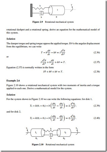
Example 2.5
A disk of moment of inertia I is rotated (see Figure 2.9) with an applied torque of T . The disk is fixed at one end through an elastic shaft. Assuming that the shaft can be modelled with a
2.1.2.1 Rotational Mechanical Systems with Gear-Train
Gear-train systems are very important in many mechanical engineering systems. Figure 2.11 shows a simple gear-train, consisting of two gears, each connected to two masses with moments of inertia I1 and I2. Suppose that gear 1 has n1 teeth and radius r1, and that gear 2 has n2 teeth and radius r2. In this analysis we assume that the gears have no backlash, they are rigid bodies, and the moment of inertia of the gears is assumed to be negligible.
The rotational displacement of the two gears depends on their radii and is given by the relationship


