PROJECT 8.2—USB-Based Microcontroller Input/Output
This project is very similar to Project 8.1, except that it includes two-way communication, while in Project 8.1 data to be output on PORTB was sent to the
microcontroller. In addition, PORTB data is received from the microcontroller and displayed on the PC.
The PC sends two commands to the microcontroller:
• Command P ¼ nT requests the microcontroller to send data byte n to PORTB.
• Command P ¼ ?? requests the microcontroller to read its PORTB data and send it as a byte to the PC. The PC then displays this data on the screen. The microcontroller sends its data in the familiar format P ¼ nT.
The hardware of this project is the same as the hardware for the previous project, shown in Figure 8.11, where eight LEDs are connected to PORTB of a PIC18F4550 microcontroller which is operated from a 8MHz crystal.
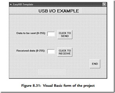
A single form is used in this project, and Figure 8.31 shows the format of this form. The upper part of the form is the same as in Project 8.1, i.e., sending data to PORTB of the microcontroller. A text box and a command button named CLICK TO RECEIVE are also placed on the form. When the button is pressed, the PC sends command P ¼ ?? to the microcontroller. The microcontroller reads its PORTB data and sends it in the format P ¼ nT to the PC where it is displayed in the text box.
Figure 8.32 shows the mikroC program of the project. The program is named USB2.C and is very similar to the one for the previous project. But here, in addition, when the command P ¼ ?? is received from the PC, the microcontroller reads PORTB data and sends it to the PC in the format using the mikroC function Hid_Write.
The program checks the format of the received command. For P ¼ ?? type commands, PORTB is configured as inputs, PORTB data is read into Write_buffer[2], and Write_buffer is sent to the PC, where Write_buffer[0] ¼ “P,” Write_buffer[1] ¼ “¼”, and Write_buffer[3] ¼ “T” as follows:
The microcontroller clock should be set as in Project 8.1 (i.e., both the CPU and the USB module should have 48MHz clocks). The other configurations bits should also be set as described in the previous problem.
Testing the Project
The project can be tested using one of the methods described in the previous project. If you are using the Visual Basic program, send data to the microcontroller and make sure the correct LEDs are turned on. Then connect some of the PORTB pins to logic 0 and click the CLICK TO RECEIVE button. The microcontroller will read its PORTB data and send it to the PC, where it will be displayed on the PC screen.
The project can also be tested using the HID terminal of mikroC IDE. The steps are:
• Start the HID terminal.
• Send a command to the microcontroller to turn on the LEDs (e.g., P ¼ 1T ) and make sure the correct LEDs are turned on (in this case, LEDs 0, 4, and 5 should turn on, corresponding to the data pattern “0011 0001”).
• Connect bits 2 and 3 of PORTB to logic 1 and the other six bits to ground.
• Send command P ¼ ?? to the microcontroller.
• The PC will display the number 12, corresponding to bit pattern “0000 1100”. The Visual Basic program listing of the project is given in Figure 8.33. Only the main
program is given here, as the library declarations are the same as in Figure 8.19. The program jumps to subroutine OnRead when data arrives at the USB bus. The format of this data is checked to be in the format P ¼ nT, and if the format is correct, the received data byte is displayed in the text box.
An installable version of the Visual Basic PC program is available in folder USB2 on the CDROM included with this book.


