PROJECT 6.4—Two-Dice Project Using Fewer I/O Pins
Project Description
This project is similar to Project 3, but here LEDs are shared, which uses fewer input/ output pins.
The LEDs in Table 6.1 can be grouped as shown in Table 6.3. Looking at this table we can say that:
• D4 can appear on its own
• D2 and D6 are always together
• D1 and D3 are always together
• D5 and D7 are always together
Thus, we can drive D4 on its own and then drive the D2,D6 pair together in series, the D1,D3 pair together in series, and also the D5,D7 pair together in series. (Actually, we
could share D1,D3,D5,D7 but this would require 8 volts to drive if the LEDs are connected in series. Connecting them in parallel would call for even more current, and a driver IC would be required.) Altogether, four lines are needed to drive the seven LEDs of each dice. Thus, a pair of dice can easily be driven from an 8-bit output port.
Project Hardware
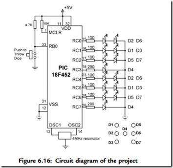
The circuit diagram of the project is shown in Figure 6.16. PORTC of a PIC18F452 microcontroller is used to drive the LEDs as follows:
• RC0 drives D2,D6 of the first dice
• RC1 drives D1,D3 of the first dice
• RC2 drives D5,D7 of the first dice
• RC3 drives D4 of the first dice
• RC4 drives D2,D6 of the second dice
• RC5 drives D1,D3 of the second dice
• RC6 drives D5,D7 of the second dice
• RC7 drives D4 of the second dice
Since two LEDs are being driven on some outputs, we can calculate the required value of the current limiting resistors. Assuming that the voltage drop across each LED
is 2V, the current through the LED is 10mA, and the output high voltage of the microcontroller is 4.85V, the required resistors are:
We will choose 100-ohm resistors.
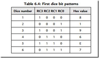
We now need to find the relationship between the dice numbers and the bit pattern to be sent to the LEDs for each dice. Table 6.4 shows the relationship between the first
dice numbers and the bit pattern to be sent to port pins RC0-RC3. Similarly, Table 6.5 shows the relationship between the second dice numbers and the bit pattern to be sent to port pins RC4-RC7.
We can now find the 8-bit number to be sent to PORTC to display both dice numbers as follows:
• Get the first number from the number generator, call this P
• Index the DICE table to find the bit pattern for low nibble (i.e., L ¼ DICE[P])
• Get the second number from the number generator, call this P
• Index the DICE table to find the bit pattern for high nibble (i.e., U ¼ DICE[P])
• Multiply high nibble by 16 and add low nibble to find the number to be sent to PORTC (i.e., R ¼ 16*U þ L), where R is the 8-bit number to be sent to PORTC to display both dice values.
Project PDL
The operation of this project is very similar to that of Project 2. Figure 6.17 shows the PDL of the project. At the beginning of the program the PORTC pins are
configured as outputs, and bit 0 of PORTB (RB0) is configured as input. The program then executes in a loop continuously and checks the state of the push-button switch. When the switch is pressed, two pseudorandom numbers between 1 and 6 are generated, and the bit pattern to be sent to PORTC is found by the method just described. This bit pattern is then sent to PORTC to display both dice numbers at the same time. The display shows the dice numbers for 3 seconds, and then all the LEDs turn OFF to indicate that the system is waiting for the push-button to be pressed again to display the next set of numbers.
Project Program
The program is called LED5.C, and the program listing is given in Figure 6.18.
At the beginning of the program Switch is defined as bit 0 of PORTB, and Pressed is defined as 0. The relationships between the dice numbers and the LEDs to be turned on are stored in an array called DICE as in Project 2. Variable Pattern is the data sent to the LEDs. The program enters an endless for loop where the state of the push-button switch is checked continuously. When the switch is pressed, two random numbers are generated by calling function Number. Variables L and U store the lower and higher nibbles of the bit pattern to be sent to PORTC. The bit pattern to be sent to PORTC is then determined using the method described in the Project Hardware section and stored in variable R. This bit pattern is then sent to PORTC to display both dice numbers at the same time. The dice numbers are displayed for 3 seconds, after which the LEDs are turned OFF to indicate that the system is ready.
Modifying the Program
The program given in Figure 6.18 can made more efficient by combining the two dice nibbles into a single table value as described here.
There are thirty-six possible combinations of the two dice values. Referring to Table 6.4, Table 6.5, and Figure 6.16, we can create Table 6.6 to show all the possible two-dice values and the corresponding numbers to be sent to PORTC.
The modified program (program name LED6.C) is given in Figure 6.19. In this program array DICE contains the thirty-six possible dice values. The program enters an endless
for loop, and inside this loop the state of the push-button switch is checked. Also, a variable is incremented from 1 to 36. When the button is pressed, the value of this variable is used as an index to array DICE to determine the bit pattern to be sent to PORTC. As before, the program displays the dice numbers for 3 seconds and then turns OFF all LEDs to indicate that it is ready.


