PROJECT 6.5—7-Segment LED Counter
Project Description
This project describes the design of a 7-segment LED-based counter which counts from 0 to 9 continuously with a one-second delay between counts. The project shows how a 7-segment LED can be interfaced and used in a PIC microcontroller project.
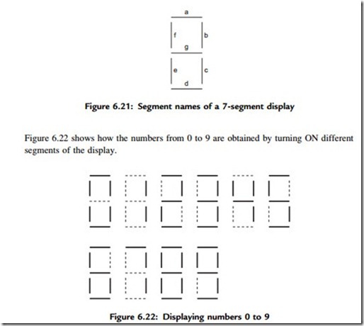
7-segment displays are used frequently in electronic circuits to show numeric or alphanumeric values. As shown in Figure 6.20, a 7-segment display consists basically of 7 LEDs connected such that the numbers from 0 to 9 and some letters can be displayed. Segments are identified by the letters from a to g, and Figure 6.21 shows the segment names of a typical 7-segment display.
7-segment displays are available in two different configurations: common cathode and common anode. As shown in Figure 6.23, in common cathode configuration, all the cathodes of all segment LEDs are connected together to the ground. The segments are turned ON by applying a logic 1 to the required segment LED via current limiting resistors. In common cathode configuration the 7-segment LED is connected to the microcontroller in current sourcing mode.
In common anode configuration, the anode terminals of all the LEDs are connected together as shown in Figure 6.24. This common point is then normally connected to the
supply voltage. A segment is turned ON by connecting its cathode terminal to logic 0 via a current limiting resistor. In common anode configuration the 7-segment LED is connected to the microcontroller in current sinking mode.
In this project, a Kingbright SA52-11 red common anode 7-segment display is used. This is a 13mm (0.52 inch) display with ten pins that includes a segment LED for the decimal point. Table 6.7 shows the pin configuration of this display.
Project Hardware
The circuit diagram of the project is shown in Figure 6.25. A PIC18F452 type microcontroller is used with a 4MHz resonator. Segments a to g of the display are connected to PORTC of the microcontroller through 290-ohm current limiting resistors. Before driving the display, we have to know the relationship between the numbers to be displayed and the corresponding segments to be turned ON, and this is shown in Table 6.8. For example, to display number 3 we have to send the hexadecimal number 0x4F to PORTC, which turns ON segments a,b,c,d, and g. Similarly, to display number 9 we have to send the hexadecimal number 0x6F to PORTC which turns ON segments a,b,c,d,f, and g.
Project PDL
The operation of the project is shown in Figure 6.26 with a PDL. At the beginning of the program an array called SEGMENT is declared and filled with the relationships between the numbers 0 and 9 and the data to be sent to PORTC. The PORTC pins are then configured as outputs, and a variable is initialized to 0. The program then enters an
endless loop where the variable is incremented between 0 and 9 and the corresponding bit pattern to turn ON the appropriate segments is sent to PORTC continuously with a one-second delay between outputs.
Project Program
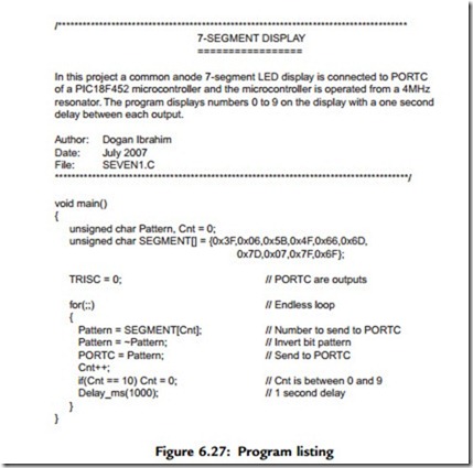
The program is called SEVEN1.C and the listing is given in Figure 6.27. At the beginning of the program character variables Pattern and Cnt are declared, and Cnt is cleared to 0. Then Table 6.8 is implemented using array SEGMENT. After configuring the PORTC pins as outputs, the program enters an endless loop using
a for statement. Inside the loop the bit pattern corresponding to the contents of Cnt is
found and stored in variable Pattern. Because we are using a common anode display, a segment is turned ON when it is at logic 0 and thus the bit pattern is inverted before it is sent to PORTC. The value of Cnt is then incremented between 0 and 9, after which the program waits for a second before repeating the above sequence.
Modified Program
Note that the program can be made more readable if we create a function to display the required number and then call this function from the main program. Figure 6.28 shows the modified program (called SEVEN2.C). A function called Display is created with an argument called no. The function gets the bit pattern from local array SEGMENT indexed by no, inverts it, and then returns the resulting bit pattern to the calling program.


