PROJECT 6.1—Chasing LEDs
Project Description
In this project eight LEDs are connected to PORTC of a PIC18F452-type microcontroller, and the microcontroller is operated from a 4MHz resonator. When power is applied to the microcontroller (or when the microcontroller is reset), the LEDs turn ON alternately in an anticlockwise manner where only one LED is ON at any time. There is a one-second delay between outputs so the LEDs can be seen turning ON and OFF.
An LED can be connected to a microcontroller output port in two different modes: current sinking and current sourcing.
Current Sinking Mode
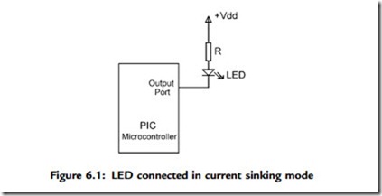
As shown in Figure 6.1, in current sinking mode the anode leg of the LED is connected to the þ5V supply, and the cathode leg is connected to the microcontroller output port through a current limiting resistor.
The voltage drop across an LED varies between 1.4V and 2.5V, with a typical value of 2V. The brightness of the LED depends on the current through the LED, and this current can vary between 8 and 16mA, with a typical value of 10mA.
The LED is turned ON when the output of the microcontroller is at logic 0 so the current flows through the LED. Assuming the microcontroller output voltage is about 0.4V when the output is low, we can calculate the value of the required resistor as follows:
Current Sourcing Mode
As shown in Figure 6.2, in current sourcing mode the anode leg of the LED is connected to the microcontroller output port and the cathode leg is connected to the ground through a current limiting resistor.
In this mode the LED is turned ON when the microcontroller output port is at logic 1 (i.e., þ5V). In practice, the output voltage is about 4.85V and the value of the resistor can be determined as:
Project Hardware
The circuit diagram of the project is shown in Figure 6.3. LEDs are connected to PORTC in current sourcing mode with eight 290-ohm resistors. A 4MHz resonator is connected between the OSC1 and OSC2 pins. Also, an external reset push button is connected to the MCLR input to reset the microcontroller when required.
Project Program
The program is named as LED1.C, and the program listing is given in Figure 6.5. At the beginning of the program PORTC pins are configured as outputs by setting TRISC ¼ 0. Then an endless for loop is formed, and the LEDs are turned ON alternately in an anticlockwise manner to create a chasing effect. The program checks continuously so that when LED 7 is turned ON, the next LED to be turned ON is LED 0.
This program can be compiled using the mikroC compiler. Project settings should be configured to 4MHz clock, XT crystal mode, and WDT OFF. The HEX file (LED1.HEX) should be loaded to the PIC18F452 microcontroller using either an in-circuit debugger or a programming device.
Further Development
The project can be modified such that the LEDs chase each other in both directions. For example, if the LEDs are moving in an anticlockwise direction, the direction can be changed so that when LED RB7 is ON the next LED to turn ON is RB6, when RB6 is ON the next is RB5, and so on.


