PROJECT 6.9—Calculator with Keypad and LCD
Project Description
Keypads are small keyboards used to enter numeric or alphanumeric data into microcontroller systems. Keypads are available in a variety of sizes and styles, from 2 x 2 to 4 x 4 or even bigger.
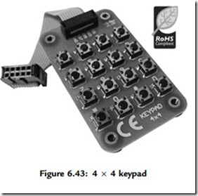
This project uses a 4 x 4 keypad (shown in Figure 6.43) and an LCD to design a simple calculator.
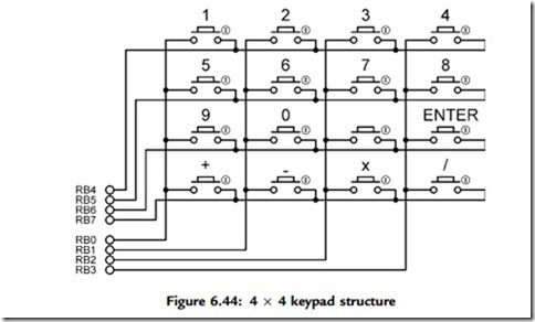
Figure 6.44 shows the structure of the keypad used in this project which consists of sixteen switches formed in a 4 x 4 array and named numerals 0–9, Enter, “þ”, “.”, “-”, “*”, and “/”. Rows and columns of the keypad are connected to PORTB of a microcontroller which scans the keypad to detect when a switch is pressed. The operation of the keypad is as follows:
• A logic 1 is applied to the first column via RB0.
• Port pins RB4 to RB7 are read. If the data is nonzero, a switch is pressed. If RB4 is 1, key 1 is pressed, if RB5 is 1, key 4 is pressed, if RB6 is 1, key 9 is pressed, and so on.
• A logic 1 is applied to the second column via RB1.
• Again, port pins RB4 to RB7 are read. If the data is nonzero, a switch is pressed.
If RB4 is 1, key 2 is pressed, if RB5 is 1, key 6 is pressed, if RB6 is 1, key 0 is pressed, and so on.
• This process is repeated for all four columns continuously.
In this project a simple integer calculator is designed. The calculator can add, subtract, multiply, and divide integer numbers and show the result on the LCD. The operation of the calculator is as follows: When power is applied to the system, the LCD displays text
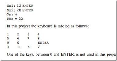
“CALCULATOR” for 2 seconds. Then text “No1:” is displayed in the first row of the LCD and the user is expected to type the first number and then press the ENTER key. Then text “No2:” is displayed in the second row of the LCD, where the user enters the second number and presses the ENTER key. After this, the appropriate operation key should be pressed. The result is displayed on the LCD for five seconds and then the LCD is cleared, ready for the next calculation. The example that follows shows how numbers 12 and 20 can be added:
Project Hardware
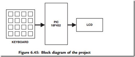
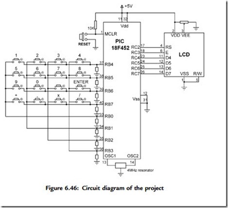
The block diagram of the project is shown in Figure 6.45. The circuit diagram is given in Figure 6.46. A PIC18F452 microcontroller with a 4MHz resonator is used in the project. Columns of the keypad are connected to port pins RB0–RB3 and rows are connected to port pins RB4–RB7 via pull-down resistors. The LCD is connected to PORTC in default mode, as in Figure 6.39. An external reset button is also provided to reset the microcontroller should it be necessary.
Project PDL
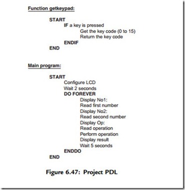
The project PDL is shown in Figure 6.47. The program consist of two parts: function getkeypad and the main program. Function getkeypad receives a key from the keypad. Inside the main program the two numbers and the required operation are received from the keypad. The microcontroller performs the required operation and displays the result on the LCD.
Project Program
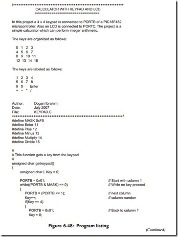
The program listing for the program KEYPAD.C is given in Figure 6.48. Each key is given a numeric value as follows:
The program consists of a function called getkeypad, which reads the pressed keys, and the main program. Variable MyKey stores the key value (0 to 15) pressed, variables Op1 and Op2 store respectively the first and second numbers entered by the user. All these variables are cleared to zero at the beginning of the program. A while loop is then formed to read the first number and store in variable Op1. This loop exits when the user presses the ENTER key. Similarly, the second number is read from the keyboard in a second while loop. Then the operation to be performed is read and stored in variable MyKey, and a switch statement is used to perform the required operation and store the result in variable Calc. The result is converted into a string array using function LongToStr. The leading blank characters are then removed as in Project 8. The program
displays the result on the LCD, waits for five seconds, and then clears the screen and is ready for the next calculation. This process is repeated forever.
Function getkeypad receives a key from the keypad. We start by sending a 1 to column 1, and then we check all the rows. When a key is pressed, a logic 1 is detected in the corresponding row and the program jumps out of the while loop. Then a for loop is used to find the actual key pressed by the user as a number from 0 to 15.
It is important to realize that when a key is pressed or released, we get what is known as contact noise, where the key output pulses up and down momentarily, producing a number of logic 0 and 1 pulses at the output. Switch contact noise is usually removed either in hardware or by programming in a process called contact debouncing. In software the simplest way to remove the contact noise is to wait for about 20ms after a switch key is pressed or switch key is released. In Figure 6.46, contact debouncing is accomplished in function getkeypad.
Program Using a Built-in Keypad Function
In the program listing in Figure 6.48, a function called getkeypad has been developed to read a key from the keyboard. The mikroC language has built-in functions called Keypad_Read and Keypad_Released to read a key from a keypad when a key is pressed and when a key is released respectively. Figure 6.49 shows a modified program (KEYPAD2.C) listing using the Keypad_Released function to implement the preceding calculator project. The circuit diagram is the same as in Figure 6.46.
Before using the Keypad_Released function we have to call the Keypad_Init function to tell the microcontroller what the keypad is connected to. Keypad_Released detects when a key is pressed and then released. When released, the function returns a number between 1 and 16 corresponding to the key pressed. The remaining parts of the program are the same as in Figure 6.48.

