In this chapter we shall look at the design of a digital controller for a control system, namely a liquid level control system.
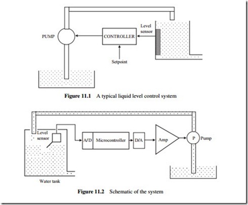
Liquid level control systems are commonly used in many process control applications to control, for example, the level of liquid in a tank. Figure 11.1 shows a typical liquid level control system. Liquid enters the tank using a pump, and after some processing within the tank the liquid leaves from the bottom of the tank. The requirement in this system is to control the rate of liquid delivered by the pump so that the level of liquid within the tank is at the desired point. In this chapter the system will be identified from a simple step response analysis. A constant voltage will be applied to the pump so that a constant rate of liquid can be pumped to the tank. The height of the liquid inside the tank will then be measured and plotted. A simple model of the system can then be derived from this response curve. After obtaining a model of the system, a suitable controller will be designed to control the level of the liquid inside the tank.
THE SYSTEM SCHEMATIC
The schematic of the liquid level control system used in this case study is shown in Figure 11.2. The system consists of a water tank, a water pump, a liquid level sensor, a microcontroller, a D/A converter and a power amplifier.
Water tank. This is the tank where the level of the liquid inside is to be controlled. Water is pumped to the tank from above and a level sensor measures the height of the water inside the tank. The microcontroller controls the pump so that the liquid is at the required level. The tank used in this case study is a plastic container with measurements 12 cm × 10 cm × 10 cm.
Water pump. The pump is a small 12 V water pump drawing about 3 A when operating at the full-scale voltage. Figure 11.3 shows the pump.
Level sensor. A rotary potentiometer type level sensor is used in this project. The sensor consists of a floating arm connected to the sliding arm of a rotary potentiometer. The level of the floating arm, and hence the resistance, changes as the liquid level inside the tank is changed. A voltage is applied across the potentiometer and the change of voltage is measured across the arm of the potentiometer. The resistance changes from 430Q when the floating arm is at the bottom (i.e. there is no liquid inside the tank) to 40 Q when the arm is at the top. The level sensor is shown in Figure 11.4.
Microcontroller. A PIC16F877 type microcontroller is used in this project as the digital controller. In general, any other type of microcontroller with a built-in A/D converter can be used. The PIC16F877 incorporates an 8-channel, 10-bit A/D converter.
D/A converter. An 8-bit AD7302 type D/A converter is used in this project. In general, any other type of D/A converter can be used with similar specifications.
Power amplifier. The output power of the D/A converter is limited to a few hundred mil- liwatts, which is not enough to drive the pump. An LM675 type power amplifier is used to increase the power output of the D/A converter and drive the pump. The LM675 can provide around 30 W of power.
