ELECTRICAL SYSTEMS
The basic building blocks of electrical systems are the resistor, inductor and capacitor (Fig- ure 2.13). The input to an electrical system may be the voltage, V , and current, i .
The relationship between the voltage across a resistor and the current through it is given by
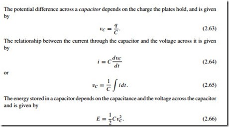
The potential difference across a capacitor depends on the charge the plates hold, and is given by
Electrical circuits are modelled using Kirchhoff’s laws. There are two laws: Kirchhoff’s current law and Kirchhoff’s voltage law. To apply these laws effectively, a sign convention should be employed.
Kirchhoff’s current law The sum of the currents at a node in a circuit is zero, i.e. the total current flowing into any junction in a circuit is equal to the total current leaving the junction.


