Test 7. LED turn on after pressing switch on RB4
In the loop two routines are called: turning LED on and off. Both routines call also routine for delaying, generating delay of 48.6 ms:
Tcm x 3 cycles x op = 108 us x 3 x 150 = 48.6 ms
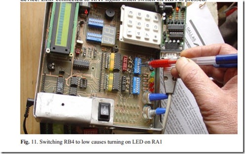
On the picture below on the evaluation board, at the right down side there are two 8 bit ports: port A and above port B. The pencil points to port B. All port B lines are on HIGH, except of line RB4. Diodes attached to port B are lighting, but LED attached to RB$ is off, because the switch connected to RB4 is pressed down. After pressing any of RB4 – RB7 switches the LED on RA1 get lighted.
If no switch is depressed (high on particular port B line) then, in the lin4 loop, af- ter the conditional instruction:
the next instruction (goto zapal) is omitted. Forcing low on RB4 causes executing next instruction and turning LED on RA1 on.
We see two LEDs lighting on PORT A: on RA5, which is input only port, always kept high. When this pin is configured as ~MCLR, is an active low Reset to the device. LED connected to RA1 lights when switch on RB4 is pressed.


