Test 11. Driving a 7-Segment LED Display with PIC16F628 microcontroller (cont.)
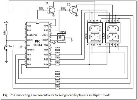
Our board is containing a dual 7 segment LED display. The display is a common catode type, so to light a segment we need to take the relevant segment high and the common cathode must be connected to the 0V rail. In order to reduce the I/O count we’re multiplexing the display digits.
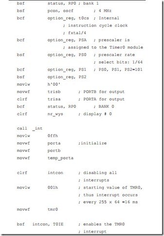
Program prints two digits: ‘0 1’ on two 7seg displays in multiplex mode. Displays are multiplexed with a frequency of 61 Hz:
T multipl. = 1 us * 64 (prescaler) * 256 (counter) = 16 384 1/T = appr. 61 Hz
Each display is turned on at a such rate, that persistence of vision of our eye thinks the display is turned on the whole time. As each display is turned on, the appropriate information must be delivered to it so that it will give the correct read- ing. Therefore, the program has to ensure the proper timing, else the unpleasant blinking of display will occur.
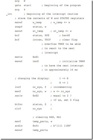
Displaying digits is carried out in multiplex mode which means that the microcontroller alternately prints on first and on the second display. TMR0 interrupt serves for generating a time period, so that the program enters the interrupt routine every 16 ms and performs multiplexing. In the interrupt routine, first step is deciding which segment display should be turned on. In case that the first display was pre- viously on, it should be turned off, set the mask for printing the digit on next 7seg display which lasts 16 ms, i.e. until the next interrupt.
Operating the device is fairly straight forward. By selectively connecting a digit- select line (one of the 2 common cathodes) to ground and applying a positive volt- age to any of the segment-select lines (common anode), it is possible to illuminate any segment of any digit. Port B on the PIC16F628 is 8 bits wide: one bit for each segment.
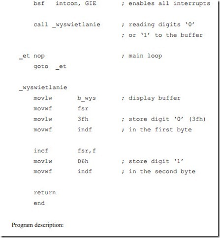
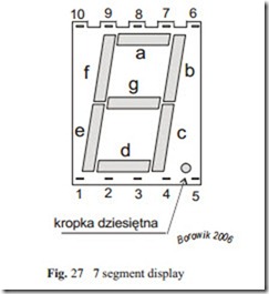
For displaying digit ‘0’ we have to turn on the following segments of the display: a, b, c, d, e, f. Into port B we have to put the value binary: b’00111111’, hexa- decimaly: 0x3f.
For displaying digit ‘1’ we have to turn on the segments b and c. Into port B we have to put the value binary: b’00000110’, hexadecimaly: 0x06.
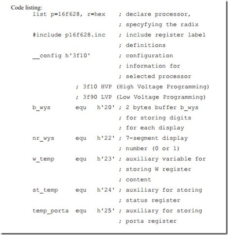
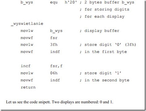
Both values in the routine _wyswietlanie we put into RAM memory to the
variable b_wys, denoting the display buffer.
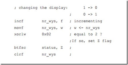
After incrementing display # 0 becomes # 1. That is OK.
Incrementing display number 1 gives #2. We detect this by xoring nr_wys (display #) with the value of 2 (0x02). Then we clear it, so display # 1 becomes # 0.
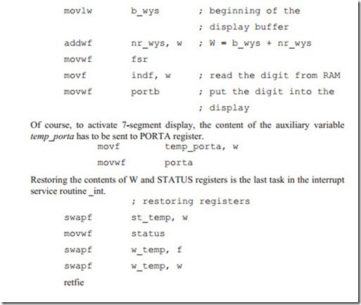
We put to ground common cathodes of both displays, and save this setting to aux- iliary variable temp_porta.. Now we have to send the appropriate digit pattern to port B. Both digit patterns are stored in RAM memory in the INDF register. The first digit: 0 (the pattern is 3fh or b’0011 1111’) has the memory address h20. The next digit: 1 (the pattern 06h or b’0000 0110’) occupies the next memory location.
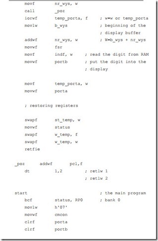
In above two lines we load the display # into W register. Then we call subroutine _poz. If the display # was 0, we receive in W on return value of 1. If the display # was 1, we receive in W on return value of 2.
This value in W register is then ored with temp_porta register in order to turn off one of two 7-segment displays. If the W register was 1, the RA0 receives value of 1, turning the attached to it 7-segment display off. If the W register was 2, the RA1 receives value of 1, turning the attached to it 7-segment display off.
Then the address in RAM memory of the digit pattern to be displayed is com- posed. To the address of the display buffer b_wys, which is 0x20 we add the dis- play #, which is 0 or 1. Thus W now points to the digit pattern of ‘0’ (0x3F) or to the digit pattern of ‘1’ (0x06). Contents of W register is then moved to the File Se- lect Register and appropriate digit pattern can be read from the indf register. Ob- tained digit pattern is next put into port B.
