Test 10. Driving a 7-Segment LED Display with PIC16F628 microcontroller
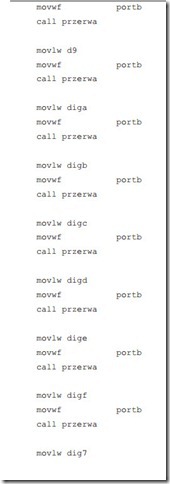
Below presented application was run on the prototype board Microcon4. The application can be used for testing all 8 lines connecting port B with the display and the display itself. 16 hexadecimal digits 0 – F are shown sequentialy one after an- other with time span 0.9s each.
B. Borowik, Interfacing PIC Microcontrollers to Peripherial Devices, Intelligent Systems, 39
Control and Automation: Science and Engineering 49, DOI 10.1007/978-94-007-1119-8_10,
The circuit is very simple. Port A, bits 0-4 are connected to the digit select lines directly. Port B, bits 0-7 are connected to the segment select lines through 330 Ω resistors. A 4MHz crystal resonator is connected to the OSC1/CLKIN and OSC2/CLKOUT pins of the PIC, with the center lead connected to Gnd. Vss and Vdd are connected to Gnd and +5V, respectively.
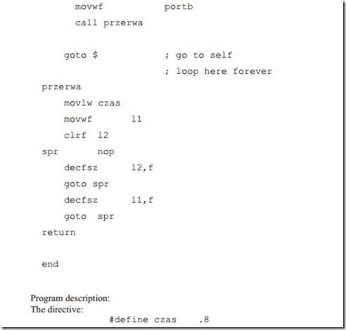
defines value of 8 decimal for register variable czas.
In the MPASM assembler (the assembler) that provides a platform for developing assembly language code for Microchip’s PICmicro microcontroller (MCU) fami- lies, a decimal integer is `d’ or `D’ followed by one or more decimal digits `0123456789′ in single quotes, or, a decimal integer is `.’ followed by one or more decimal digits `0123456789′.
The directives:
are used to assign a variable names l1 and l2 to an address locations in RAM re- spectively h’20’ and h’21’.
Routine przerwa contains nested loop. Two general purpose registers l2 and l1 are decremented. l2 is first cleared and then is decremented in the inner loop with in- struction decfsz (decrement f, skip if zero). The loop is executed 256 times. It takes time of 110.592ms (256 x 4 x 108us).
4 accounts for 4 machine cycles:
 Nop instruction adds up to the number of machine cycles in one iteration.
The segments in a 7-segment display are arranged to form a single digit from 0 to F as shown in the figure:
Segments 0 to 7 are marked respectively with non-capital letters: a, b, c, d, e, f, g and dp, where dp is the decimal point. The 8 display segments lines (0 to 7) are connected to the 8 PortB lines. PORTB is made output by clearing TRISB regis- ter.
In order to reduce the number of pins in the device, a clever arrangement of com- mon cathode is employed. Since there are 8 segments (7 plus the decimal point), there are 8 anode connections. Onto the PORTB are put respective values, repre- senting particular digits from 0 to F and at the last: the decimal point. Those val- ues were defined at the beginning of the program.
Value 1 means the respective LED segment is turned on. To display 8 we need to put a binary b’01111111′ on PortB. This will turn on all the LEDs except the decimal point. The number 0 is simply an 8 with the middle segment off, b’00111111′. The decimal point has its value: b’10000000’.


