UNDERSTANDING THE MICROCHIP TECHNOLOGY PIC 16F877A: FEATURES OF THE MCU
PIC microcontrollers are manufactured by the Microchip Technology Corporation of Chandler, Arizona.
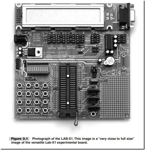
We will be using the recommended 16F877A microcontroller in the LAB-X1 board, see Figure 3.1. Not all the features provided in the 16F877A will be addressed in the exercises to follow, but enough will to give you the confidence and understanding you need to proceed on your own. In more technical terms, this MCU has the following core features (this list was reduced and modified from description by Microchip Technologies):
N High-performance RISC CPU
N Operating speed: DC-20 MHz clock input
N DC-200 ns instruction cycle
N Up to 8K s 14 words of FLASH program memory
N Up to 368 s 8 bytes of data memory (RAM)
N Up to 256 s 8 bytes of EEPROM data memory
N Interrupt capability (internal and external)
N Power-on Reset (POR)
N Power-up Timer (PWRT) and Oscillator Start-up Timer (OST)
N Watchdog Timer (WDT) with its own on-chip RC
N Programmable code-protection
N Power-saving sleep mode
N Selectable oscillator options
N Low-power, high-speed CMOS FLASH/EEPROM technology
N Fully static design
N In-circuit Serial Programming (ICSP) via two pins N Single 5V In-Circuit Serial Programming capability N In-Circuit debugging via two pins
N Processor read/write access to program memory
N Wide operating voltage range: 2.0 to 5.5V
N High sink/source current: 25 mA
N Commercial and industrial temperature ranges
N Lowpower consumption
This MCU has the following peripheral features:
N Timer 0: 8-bit timer/counter with 8-bit pre-scaler
N Timer 1: 16-bit timer/counter with pre-scaler. It can be incremented during sleep via external crystal/clock
N Timer 2: 8-bit timer/counter with 8-bit period register, pre-scaler, and post-scaler
N Two PWM modules, maximum resolution 10 bits
N 10-bit multichannel analog-to-digital converter
N Synchronous Serial Port (SSP)
N Universal Synchronous Asynchronous Receiver Transmitter (USART)
N Parallel Slave Port (PSP), 8-bit wide
N Brown-out detection circuitry for Brown-out Reset (BOR)
This MCU is described in profuse detail in a more than two hundred-page data sheet that you can download from the Microchip website at no charge. The data sheet is a PDF document that you should have available to you at all times (maybe even open in its own window, ready for immediate access) whenever you are programming the 16F877A. The Adobe software you need to read (but not write) PDF files is also avail- able at no charge on the web. You should have the a copy of the latest version of this very useful software on your computer.
We will not cover the entire data sheet in the exercises, but we will cover the most commonly used features of the MCU (especially the ones relevant to the LAB-X1). After doing the exercises you should be comfortable with reading the data sheet and finding the information you need to get your work done.
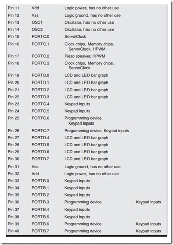
In this particular case, the LAB-X1 board, the MCU is already connected to the items on the board. Therefore, if you want to use the LAB-X1 for your own hard- ware experiments you must use the MCU pins in a way compatible with the com- ponents that are already connected to them. Often, even though the pin is being used in the LAB-X1 circuitry, you can drive something else with it without adversely affecting your experiment (depending on the load being added). Refer to Table 3.1 to quickly determine if the pin and port you want to use is free or how it is being used.


