COUNTERS
Of the three timers in the 16F877A, only Timer0 (an 8-bit timer) and Timer1 (the 16-bit timer) can be used as counters. Timer2 does not have a counter input line. Generally speaking this makes Timer0 suitable for use with small counts and rapid interrupts and Timer1 suitable for larger counts.
HOW DOES A COUNTER WORK?
The operation of a counter is similar to the operation of a timer except that instead of getting its count from an internal clock or oscillator, the counter gets its signals from an outside source. This means we have to do the following to use a counter:
N Decide which counter (timer) to use.
N Tell the counter where the signal is coming from.
N Tell it whether to count on a rising or falling edge of the signal.
N Decide what target count we are looking for, if applicable.
N Tell the counter where to start counting (because the interrupt will occur when the counter gets full).
N Decide whether we will need to scale the count by setting the scaler(s).
Once you start a counter, the counting continues until you deactivate it. There is no way to stop it or any purpose in doing so. It will reset if the MCU is reset, and it can
be reset by writing to it. The rest has to do with knowing what bits to set in the control registers to get the counters to operate in the way we want them to.
USING TIMER0 AS A COUNTER
The three registers used to control the operation of the Timer0 module are TMR0, INTCON, and OPTION_REG. The interrupt control register is INTCON. See the data sheet.
Note Though often called Timer0 and referred to as Timer0 here and in the data sheet, the real designation of this timer address is TMR0.
This counter has the following properties:
N 8-bit timer/counter.
N Readable and writable.
N 8-bit software programmable pre-scaler.
N Internal or external clock select.
N Interrupt on overflow from FF (hex) to 00 (hex).
N Edge selection available for external clock signal.
N Counter mode is selected by setting OPTION_REG.5=1.
N External input for the timer must come in on PORTA.4 (pin 6 on the PIC).
N The edge direction is selected in OPTION_REG.4 (1=Rising edge).
N The pre-scaler is assigned with bits 0 to 3 of the OPTION_REG register (Chapter 5).
Note The Watchdog Timer cannot use the pre-scaler when the pre-scaler is being used by Timer0.
Since this is an 8-bit counter, it is suited to the counting a small number of counts, but longer counts can be accommodated by creating a routine to keep track of the number of interrupts.
Let us use the counter to count the pulses received from a 42-slot encoder mounted on a small DC motor. This same source will be used later for the Timer1 experiment for comparison between counters. (This motor will also be used later on as the encoded servomotor for the servo control experiments.)
We will set up the LCD display so that we can display certain registers during the operation of the program. We will also set the program up to read the potentiometers so that we can use their values to modify the program as the motor runs. Only POT0 and POT1 are used in this program.
Put these and other values in the program and run the program. See what happens.
USING TIMER1 AS A COUNTER
The operation of Timer1 as a counter is similar to the operation of Timer0. However, because Timer1 is a 16-bit timer, much longer counts can be handled and counts com- ing in at faster rates can be counted. It also means that a lot more can be done in the TimerLoop and BlinkerLoop routines if the program is designed to do so. However, the set up for Timer1 is more complicated because of the more numerous options available.
The differences between the use of the two timers have to do with the setup of the controlling registers. Timer1 is controlled by six registers, compared to the three for Timer0. Timer1’s registers are as follows:
Again, and as always, the frequency of the oscillator is divided by 4 before being fed to the counter when you use the internal clock.
Page 52 of data sheet describes how Timer0 is used with an external clock. Counter mode is selected by setting bit TMR1CS. In this mode, the timer increments on every rising edge of clock input on pin RC1/T1OSI/CCP2, when bit T1OSCEN is set, or on pin RC0/T1OSO/T1CKI, when bit T1OSCEN is cleared.
Three of the pins on the 16F877A can be used as inputs to the Timer1 counter module:
N Pin PORTA.4, the external clock input (pin 6 on the PIC)
N Pin PORTC.0, selected by setting TIOSCEN =1
N Pin PORTC.1, selected by setting TIOSCEN=0
Timer1 is enabled by setting T1CON.0=1. It stops when this bit is turned off or disabled.
The clock that Timer1 will use is selected by T1CON.1. The external clock is selected by setting this to 1. The input for this external clock must be on PORTA.4.
In summary, eight bits in Timer1 control register T1CON, which provides the fol- lowing functions:
N Bit 7: Not used and read as a 0 N Bit 6: Not used and read as a 0 N Bit 5: Input pre-scaler
N Bit 4: Input pre-scaler
N Bit 3: Timer1 oscillator enable
N Bit 2: Timer1 external clock synchronization
N Bit 1: Timer1 clock select
N Bit 0: Timer1 enable
If the interrupts are not going to be used all the other registers can be ignored, and we can set:
T1CON to %00110001
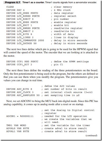
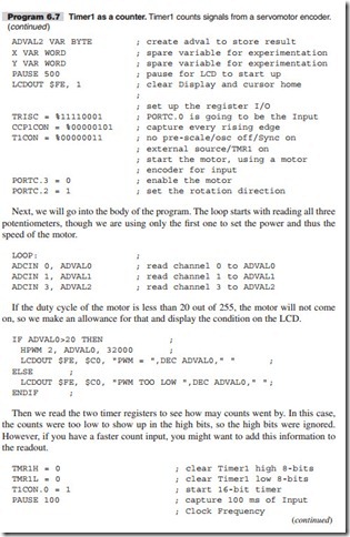
The setting of these bits is described in detail in Chapter 5 of the data sheet. Program 6.7 reflects this discussion.
First let us define all the defines that we will need. Here all the defines are included as an example, but not all are needed when using the LAB-X1.


