Temperature Controller Test Program
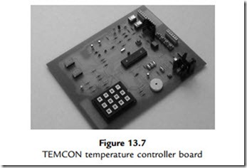
Program 13.1 was written to exercise the hardware and to get started in developing applications for the TEMCON2 system, using hardware built to this design or the simulation download.
The program will read in the analogue inputs (select the test inputs by setting the dual in-line (DIL) switches on) and display the raw data on the displays. Pressing a key on the keypad will select an analogue input for display, key ‘1’ for input 1, and so on to ‘4’, then repeating for keys 5e8. An apparently random pattern results, which changes if the test pots are varied, indicating that the hardware input and display interfaces are working. Key 9 will sound the buzzer, while ‘*’,‘0’ and ‘#’ will operate the heater, vent and fan, respectively. A full header has been included with as much information as possible: details of the target system, program description, register initialization, port allocation and so on.
The routine to read in an analogue input is based on the model routine provided in the data sheet, with 20 ms settling time. The conversion is started by setting the GO bit in the ADC control register, and then waiting for it to be cleared by the ADC to indicate that the conversion is complete. In this program, only 8 of the 10 bits of the ADC result are used, so the result is ‘right justified’ to place the least significant 8 bits in the ADRESL register for output to the display. Note that ADRESL is in bank 1 in the 16F887, requiring this bank to be selected and deselected as necessary. In a working program, the analogue input value would be converted into a two-digit decimal value for the display. Using the conversion scaling calculated above,
a temperature of 50oC would give a result of 250 (in binary) in ADRESL, with the result right justified. Only a quarter of the ADC range is then being used, because the input range is only 500 mV. This result can then be converted into the corresponding display digits ‘5’ and ‘0’, and so on down to zero.
The keyboard scanning routine uses a simple method to check if each key in each row has been pressed, then calls the required action. A more elegant and compact keyboard scanning method is possible when reading in numerical values. A full working program would allow the user to enter the maximum and minimum values for the target temperature, and then go into run mode, where the temperature would be controlled within the set range by operation of the heater, vent and fan. An outline of this application is shown in Program 13.2.


