Production Systems
There are two main types of production system. Manufacturing systems include materials and component handling technologies such as conveyors and robots, which work with machine
tools and assembly subsystems to produce discrete product items, such as motor vehicles. Process control systems are those that supervise continuous flow production, such as an oil refinery, where the product is a liquid, gas, powder, granules or similar material. This typically involves sequence control of pumps and valves, controlling storage tanks and pipework installations, with inputs from flow, level, temperature sensors, etc., to form a closed loop system. All these systems will contain microprocessor-based controllers, both within the PLCs that control the component subsystems, and within the dedicated controllers built into machines, tools and robots.
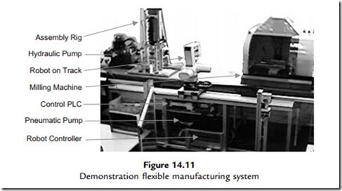
A flexible manufacturing system (FMS) workcell has machines that can be reprogrammed to produce a variety of similar products. Typically, it consists of pick-and-place robots working alongside machine tools to manufacture components and assemble them into a finished product. A basic demonstration system is shown in Figure 14.11. It consists of a milling machine, a hydraulic assembly rig and a component handling robot. It is designed to machine and assemble a simple product consisting of three components: a printed circuit board (PCB) in a milled plastic enclosure with a press-fit cover. The robot places a plastic blank in the mill, which machines the casing; the robot then retrieves the enclosure, places it in the assembly rig and inserts the PCB, and the cover is fitted by the hydraulic press.
A block diagram (Figure 14.12) shows how the subsystems of the workcell interconnect. The digital signals in the system operate at 24 V, the higher voltage providing better noise immunity than TTL (5 V) levels. The various controllers signal to each other with, usually, individual active low signals, to control the sequence of operations. For example, when the mill has finished, it asserts (sets active) a ‘Mill Ready’ signal to the robot controller, which triggers the robot program to pick up the finished workpiece. The robot slide, the press rig and the mill are all controlled by their own PLCs, with the main PLC in charge of the overall system. The robot
controller needs a reasonably powerful processor system, because of the complex calculations required for the robot movement. This and the PLCs are programmed from a PC, via a serial port. The main system PLC remains connected to the PC, which then operates as a supervisory control and data acquisition (SCADA) system host when the system is running. It provides a virtual control panel and graphical status display of the system as it runs, reading status bits and writing control bits in the main PLC, and modifying the display accordingly.
Both manufacturing and process control systems can be managed by a SCADA network to provide integrated, centralized control and performance monitoring. A typical display is shown in Figure 14.13. Powerful software suites support the communication and presentation of the information, principally using on-screen interactive mimic diagrams and dynamic database management to give a complete overview of the system operation.
In the industrial environment, the subsystems need to be mounted and connected together using physically robust methods. A typical control cabinet is shown in Figure 14.14. The vulnerable parts of the control system, such as PLCs, microcontroller boards, terminal blocks, power supplies, communication modules and keypads, are protected in a steel cabinet. Another important feature is the emergency stop buttons.


