DIZI Application Outlines
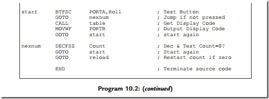
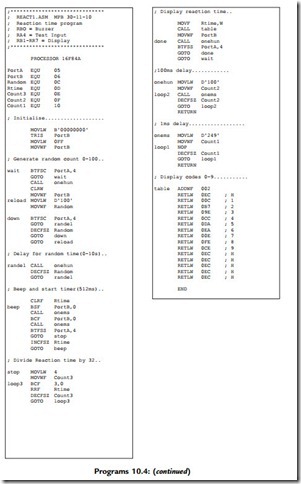
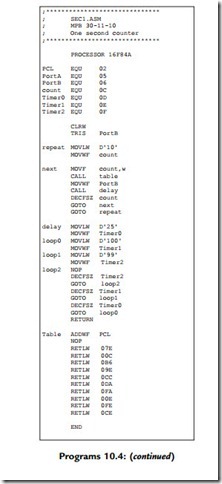
A further eight applications are specified below, and the source code for each is listed in
Programs 10.4. They can be downloaded from www.picmicros.org.uk, and tested in simulation
mode in MPSIM or ISIS (if available). If the DIZI hardware is constructed, they can be programmed into a 16F84A chip using an out-of-circuit programmer.
HEX1 Hex Converter
The hexadecimal number corresponding to the binary setting of the DIP switch inputs is displayed. The input switches select from a table of 16 seven-segment codes which drive the display in the required pattern for each hex digit: 0, 1, 2, 3, 4, 5, 6, 7, 8, 9, A, b, C, d and E. Note that numbers B and D are displayed in lower case so that they can be distinguished from 8 and 0, respectively.
MESS1 Message Display
A sequence of characters is displayed for about 0.5 s each. Most letters of the alphabet can be obtained on the seven-segment display in either upper or lower case, for instance ‘HELLO’. The number of characters must be set in a counter, or a termination character used.
SEC1 Second Counter
An output is displayed which counts down exactly once per second, from 0 to 9, and then repeats. A table of display codes is required as in the Hex Converter application. A 1 s time delay can be achieved using the hardware timer (Chapter 6) and spare register. A tick could be produced at the audio output by pulsing the speaker at each step.
REACT1 Reaction Timer
The user’s reaction time is tested by generating a random delay of between 1 and 10 s, outputting a beep, and timing the delay before the input button is pressed. A number representing the time between the sound and the input, in multiples of 100 ms, should be displayed as a number 0e9, giving a maximum reaction time of 900 ms.
An audio frequency generator outputs frequencies in the range 20 Hz to 20 kHz. The sounder output is toggled with a delay between each operation determined by the frequency required, as in the BUZZ1 program. For example, for a frequency of 1 kHz, a delay of 1 ms is required, which is 1000 instruction cycles at a cycle time of 1 ms. The information on program timing must be studied in Chapter 6. The delay time, and hence the frequency, can then be incremented using the input button, and range selection with the input switches might be incorporated, as there are only 255 steps available when using an 8-bit register as the period counter.
MET1 Metronome
An audible pulse is output at a rate set by the DIP switches or input buttons. The output tick can be adjustable from, say, 1 up to 4 beats per second, using the interrupt button to step the speed up and down, and the input button to select up or down. A software loop or the TMR0 register can be used to provide the necessary time delays.
BELL1 Doorbell
A tune is played when the input button is pressed, using a program look-up table for the tone frequency and duration. Each tone must be played for a suitable time, or number of cycles, as required by the tune. The program can be elaborated by selecting a tune using the DIP switches, and displaying the number of the tune selected.
GIT1 Guitar Tuner
The program will allow the user to step through the frequencies for tuning the strings of a guitar, or another musical instrument using the input button, or selecting the tone at the DIP switches. The program could be enhanced by displaying the string number to be tuned. The tone frequencies will be generated as for the doorbell application. The digit display codes would also be required in a table.
be scanned in rows and columns. A key press is detected as a connection between a row and column. The pull-up resistors ensure that all lines default to logic ‘1’. If a ‘0’ is applied to one of the column terminals (C1, C2, C3), and a key is pressed, this ‘0’ can be detected at the row terminal (R1, R2, R3, R4). If the keypad terminals are connected to a PIC port, and a ‘0’ output in rotation to the three columns, a key can be detected as a combination of the column selected and the row detected. Column terminals can be set as outputs, and rows as inputs. Draw a flowchart to represent the process for converting each decimal key into the corresponding BCD number.
(b) A lock function may be implemented by matching an input sequence with a stored sequence of, say, four digits, and switching on an output to a door solenoid if
a match is detected. Specify the hardware and outline the program for the lock application.
(c) Design, build and test an electronic lock system using the keypad shown, a suitable PIC and an LED to indicate the state of the lock (ON ¼ unlocked). Research the design for the interface to a solenoid operated door lock.
Note: Keypad scanning is used in Program 13.1, and a lock application outlined in Appendix


