GENERATING OUTPUTS
It will be easier if we learn to control the outputs first because we can do this from programs that we write without the need for any additional hardware or input signal. We will start with the simple control of LEDs and proceed to the control of the two- line LCD that is provided on the LAB-X1, and then move on to using the speaker and an R/C hobby servo.
Let us start with the standard turning an LED on and off program. We will use one of the LEDs in the ten-LED bar graph that is provided on the LAB-X1. On the LAB-X1 we have control of only the rightmost eight LEDs on the bar graph. The leftmost LED is the power-on indicator and the one next to it comes on if we were using a common cathode arrangement (as opposed to the common anode arrangement as it is currently configured).
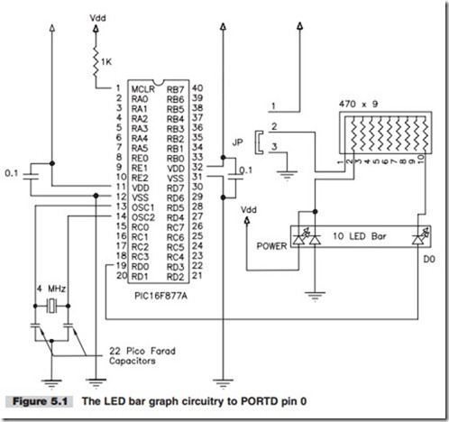
The circuitry we are interested in is shown in Figure 5.1. All other circuitry of the LAB-X1 is still in place, but we have suppressed it, as shown in the figure, so we won’t be distracted by it and can concentrate on the one LED that is of interest, PORTD.0. (PORTD.0 refers to bit 0 of PORTD.)
This is how we turn something on with a microprocessor. We will use this technique whenever we need to turn something on in our experiments. If the signal needs to be
amplified to do useful work, we will do that. Transistors, conventional relays, and solid state relays can all be controlled by TTL level signals to give us the control voltages and amperages we need.
The following paragraphs and Program 5.1 guide through your first interaction with the microcontroller. We will take all the steps necessary to write an operational program and run it on the LAB-X1. Though this is a very simple program the steps taken here will be repeated for all the programs that we will ever write. It is important that you understand each and every step undertaken here before we proceed any further.
In this first experiment, we want to control the rightmost LED of the LED array. This is connected to bit 0 of PORTD in the circuitry shown in Figure 5.1. Our program needs to turn this LED on and off to demonstrate that we have control of these two functions.
In general, the ports on the microcontrollers (MCUs) are designed so that they can be used as inputs or outputs. In fact, the ports can be programmed so that certain pins on a port are inputs and others are outputs. All we have to do is tell the program what we want done and the compiler will handle the details. The compiler not only allows you to define how you will use the pins of each port, it can also set them up as inputs or as outputs automatically, depending on the instructions that we use in our programs. You have a choice of setting PORTD to an output port and then setting pin 1 on this port high, or you can simply tell the compiler to make pin 1 of PORTD high and it will take care of the details.
The ports can be treated just like any other memory location in the microcontroller. By name, you can read them, set them, and use them in calculations and manipulations just like you can with any other named or unnamed memory location. If things are connected to the ports and pins, the program will interact with and respond to what- ever is connected to them. (Any named port, register, or pin can be addressed directly by name for all purposes when using the PBP Compiler. They are called out as they are named in the data sheet.)
BLINK ONE LED
Type Program 5.1 as follows into your PC and save it. It does not need to be saved in the same directory as the PBP.exe program. To keep the conventions being used in the compiler manual, call this program myBLINKL so that it does not overwrite the BLINK.BAS program provided on the disk that came with the LAB-X1. Program 5.1 here demonstrates the on-off control pin 0 of PORT D.
The program demonstrates the most elementary control we have over an output. In this program we did not have to set the port directions (with the TRIS command) because the HIGH and LOW commands take care of that automatically. (If we used PORTD.0=1 instead of HIGH PORTD.0 we would have to set TRISD to %11111110 first to set all lines to inputs except D0, which is here shown set as an output.)
We will use binary notation (%11110000) for setting all ports and port directions throughout this book, though you can use hexadecimal ($F0) and decimal (DEC 240) notation interchangeably. Using binary notation lets you see what each pin is doing without having to make any mental conversions.
BLINK EIGHT LEDS IN SEQUENCE
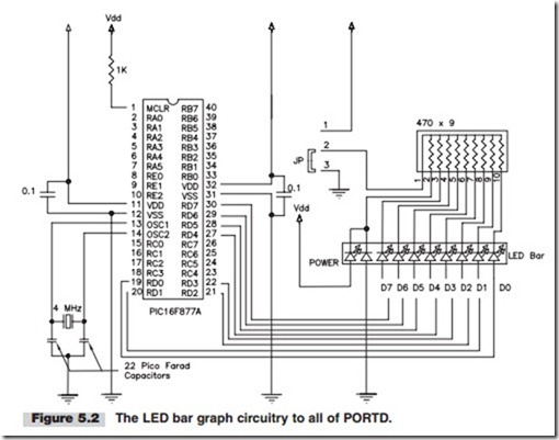
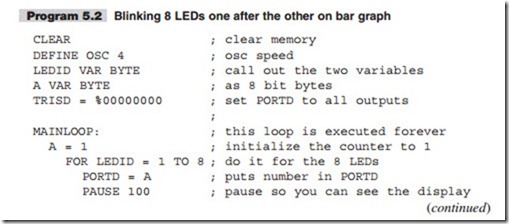
In the next experiment (Program 5.2), the circuitry for which is shown in Figure 5.2, we will blink the eight rightmost LEDs on the bar graph one LED at a time. We do this by setting PORTD to 1 and then multiplying it by two eight times to move the lighted LED left in each iteration. Note that the last multiplication overflows the 8-bit counter and turns all the LEDs off.
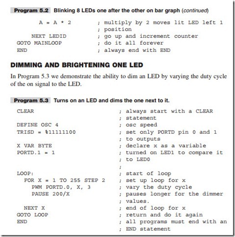
With the preceding programs we learned that we can control the on-off state and the brightness on an LED. Controlling the brightness becomes relevant when we are con- trolling seven segment displays because the LEDs in them are turned on one at a time and the duty cycle has to be managed properly to get an acceptable display within an acceptable time frame.


