PICkit2 Demo System
The PICkit2 is an in-circuit programming module that supports a full range of PIC microcontrollers. PICkit3 is now available. The PICkit2 Starter Kit also includes the LPC board incorporating the 16F690 MCU and some minimal test circuitry (Figure 7.2). The programmer is connected to the USB port of the host PC running MPLAB, with the six-pin in-line output plugged into a six-pin male connector on the target board. The connections are shown in Table 7.1.
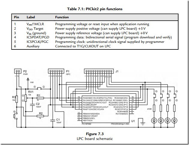
The board has four light-emitting diodes (LEDs) to display programmed output sequences, a push button connected to !MCLR and a small pot providing an analogue test input. The LPC board can be powered from the USB port via pins 2 and 3. For programming, þ12 V is applied to pin 1, but after programming is complete, it reverts to the reset (!MCLR) input function. When under control of the host PC, the on-board reset button is overridden by a command/button in the MPLAB toolbar. When detached from the programmer, the push button can be configured as a reset input or as a digital input. Pins 4 and 5 carry the program data and clock, which write the code into program memory in the target chip. Pin 6 is available for additional functions of the programmer. These features can be seen in the schematic for the LPC (Figure 7.3).
The board has additional connections to all the chip pins and a small prototyping area, which can be used to add peripheral components. Links are provided in the LED circuits so that they can be disconnected if these outputs are needed for another load. When the board is removed from the programmer, it needs to be connected to an external supply via connector P2.
