Program Implementation
When the program logic has been worked out using flowcharts, or otherwise, the source code can be entered using a text editor. Normally, the program editor is part of an integrated development package such as MPLAB. Most programming languages are now supplied as part of an integrated edit and debug package. Assembler source code can also be entered directly into the Proteus VSM system, which includes an editor and the PIC assembler, and this is preferable where the schematic has already been created in ISIS and the program is not too complex.
Flowchart Conversion
The program design method should be applied so as make the program as easy as possible to translate into source code. The PIC has a ‘reduced’ instruction set, meaning that the number of available instructions has deliberately been kept to a minimum to increase the speed of execution and reduce the complexity of the chip. While this also means that there are fewer instructions to learn, the assembler syntax (the way the instructions are put together) can be a little trickier to work out. For example, the program branch is achieved using the ‘Bit Test and Skip’ instruction. In CISC assembly code languages, branching and subroutine calls are implemented using single instructions. The PIC assembler requires two instructions. However, recall that ‘Special Instructions’ (essentially predefined macros) are available which combine ‘test’, ‘skip’ and ‘goto’ instructions to provide equivalents to conventional conditional branching instructions (see Chapter 6).
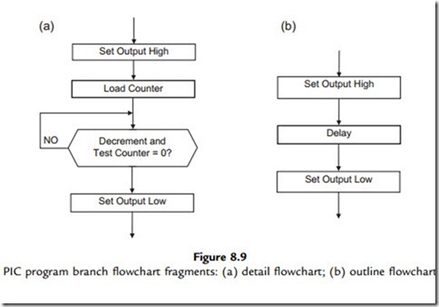
The representation of the program with different levels of detail is illustrated in Figure 8.9. Figure 8.9(a) shows the process in enough detail that each process box converts into only one or two lines of code. This may be necessary when learning the programming syntax. Later, when the programmer is more familiar with the language and the standard processes that tend to recur, such as simple loops, then a more condensed flowchart may be used, such as Figure 8.9(b), where the loop is concealed within the ‘delay’ process. As we have seen above,
this process can also be written as a separate, reusable, software component: a subroutine. The corresponding source code fragment is shown in Table 8.3.
Another limitation in PIC 16 assembler is found when moving data between registers. It is not possible to copy data directly between file registers; it has to be moved into the working register (W) first, and then into the file register. This requires two instructions instead of the single instruction available in other processors. This problem is overcome to some extent by the availability of the destination register option with the byte processing operations, which allows the result to be placed in W or F, as required. Nevertheless, the advantage of simplicity in PIC assembly language outweighs these limitations, especially in the early stages of learning.
MOT1 Source Code
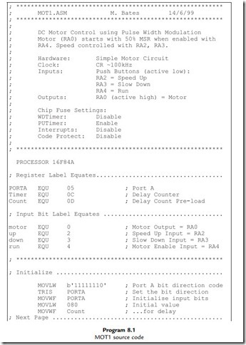
The program source code for the MOT1 program is listed in Program 8.1. The program produces the PWM output by toggling RA0 with a delay. A register labeled ‘timer’ holds the current value for the ‘on’ delay. The program does not use a subroutine for the delay, because the ‘timer’ value has to be modified for the ‘off’ delay. Note the use of the COMF instruction, which complements the contents of the timer register, which effectively subtracts the value from 256. The total PWM cycle time stays constant as a result. When incremented, the ‘timer’ value has to be checked to prevent it rolling over from FF to 00, by decrementing it again if the new value is zero. The roll-under at the low end of the scale is prevented in a similar way.
The program source code has instruction mnemonics in upper case to match the instruction set in the data sheet. However, by default, they are not case sensitive, so you will often see them in lower case. On the other hand, labels ARE case sensitive, so they must match exactly when
declared and used. The label case sensitivity can be switched off as an assembler option if you wish. Upper case characters for the special function register names (PORTA) have been used to match the register names used in the data sheet, and lower case characters with the first letter capitalized used for general purpose registers (Timer, Count). The bit labels are lower case (motor, up, down, run), as are the address labels. Using source code editing conventions like this is not obligatory, but consistent layout and presentation improves program readability and makes it easier to understand.
Most programming languages allow comments to be included in the source code as a debugging aid for the programmer, and information for other software engineers who may need to fix the code at a later date. Comments in PIC source code are preceded by a semicolon; the assembler ignores any source code text following, until a line return is detected.
A header should always be created for the main program and the associated routines. It should contain relevant information for program downloading, debugging and maintenance.
Examples have already been given. The layout should be standardized, especially in commercial products. The author’s name, organization, date, and a program version number and description are essential. Hardware information on the processor or system type is important; for example, when a PIC program is assembled, the processor type must be specified, because there is variation in the SFRs available. The processor type may be specified in the header block as an assembler directive (essential when using the bare assembler in Proteus VSM), or by selecting the processor in the MPLAB development system options. Alternatively, the standard header file can be included, which defines the MCU and registers. Target hardware details such as input and output pin allocation are useful, and the design clock speed needs to be specified in programs where code execution time is significant. Programmer settings that enable or disable hardware features such as the watchdog timer, power-up timer and code protection should also be listed, unless specified explicitly using the available assembler directives.
The general layout of the source code should be designed to make the structure clear, with subroutines headed with their own brief functional description. The asterisk symbol (*) is often used to separate and decorate comments; rows of dots are also useful, but there is some scope here for individual touches! The main object is to make the source code and program structure as easy as possible to understand. Blank lines should separate the functional program blocks; that is, instructions that together carry out an identifiable operation. In this way, the source code can be presented in a way that makes it as easy to interpret as possible.
When the program has been finalized and the memory and I/O requirements of the PIC have been established, the final choice of MCU can be made. The range of 16F devices will be reviewed in Chapter 12. When finalizing the circuit design, a more detailed consideration of a range of interfacing techniques can be found in Interfacing PIC Microcontrollers: Embedded Design by Interactive Simulation by this author (Newnes 2006).
1. Sketch a PWM waveform and explain how PWM controls the power delivered to dc
loads from a single digital output. (4)
2. Explain briefly the role of the block diagram and flowchart in creating the final hardware and software design for an application. (4)
3. Describe two alternative techniques to flowcharts for program design and one advantage of each. (4)
4. Explain the function of the following statements in the source code for MOT1, expanding on the comment given in the program source code:
(a) motor EQU 0
(b) BTFSC PORTA, run
(c) INCF Count
(d) COMF timer. (8)
1. Compare the source code for MOT1 with the flowchart in Figure 8.5, and the pseudocode in Figure 8.8, and note how they correspond. Draw a structure chart for the application using the drawing tools in Word, or equivalent word-processing application.
2. Test MOT1 in MPLAB and confirm correct operation, or in Proteus VSM if available.
3. (a) Devise a set of structured flowcharts for making a nice cup of tea, manually!
(b) Draw a block diagram of a coffee machine, and devise a set of flowcharts for a control program. You may assume a PIC microcontroller will be used with suitable
interfacing, sensors and actuators.
4. (a) Devise a block diagram for a motor control system which has a bidirectional drive, and inputs which select the motor on/off and direction of rotation. Separate active low outputs should be provided to enable the motor in each direction. Investigate full bridge driver circuits and modify the MOT1 circuit to incorporate this output stage.
(b) Modify the outline flowchart for MOT1 to operate the full bridge bidirectional output, allowing the direction to be changed only while the motor is disabled. Produce
a logic table and detail flowchart, and amend the source code observing the recommendations for source code documentation. Compare your design with that provided in Chapter 11.


