Program Testing
Preliminary hardware inspection and testing is important if the circuit is newly constructed, and essential if it is a new design. First, have a good look at the board to check that the correct components have been fitted in the correct places and orientation, there are no dry joints or solder bridges and so on. Connect the power before fitting the chip(s) if they are in sockets, and check that the supply voltages are correct, and on the right pins. When the hardware has been thoroughly checked, switch on and check that the MCU is not overheating.
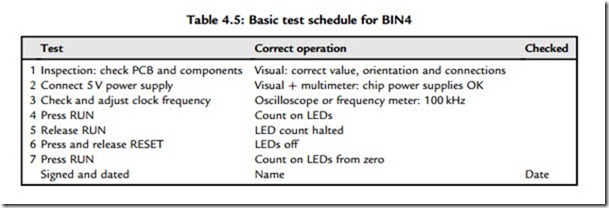
In a commercial product, a test schedule must be devised and correct operation confirmed and recorded. The test procedure should check all possible input sequences, not just the correct ones, if the design is to be completely reliable. It is quite difficult to be sure that complex programs are 100% testable, as it is often not easy to predict every possible operating sequence. An outline test procedure for BIN4 is suggested in Table 4.5.
The program should start immediately on power-up. If it does not function correctly when tested against the original specification, a fault-finding process needs to be followed, as outlined below.
1. Download the supporting documentation for MPLAB from www.microchip.com. Study the tutorial in the User’s Guide and the help files supplied with MPLAB as necessary to familiarize yourself with editing, assembling and simulating an application program. Start up MPLAB, create a source code file for BIN3, and enter the assembler code program, leaving out the comments. Assemble, correct any errors and simulate. Check that the port B (F6) file register operates as required.
2. Modify the program as BIN4, and confirm that its operation is essentially the same.
3. Modify the program to scan the output, that is, move one lit LED along the display, repeating indefinitely, using a rotate instruction.
4. Construct a prototype circuit, download BIN4 and test to the schedule given in Table 4.5.
Refer forward to Chapter 10 if necessary.
5. If Proteus VSM is available, enter or download the schematic and source code for application BIN4 from www.picmicros.org.uk. Assemble the source code, attach the hex file to the MCU and check that the simulation works (LEDs flash). Adjust the program to give an output period of exactly 50 ms at RB0. Use NOPs in the code if necessary. Use the virtual oscilloscope and timer counter to check the output period, and the logic analyzer to display all the outputs simultaneously.

