Microcontroller Application Design
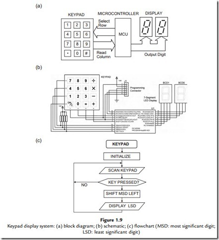
A simple microcontroller-based equivalent of the word-processing application described above is shown in Figure 1.9. The purpose of the system is to store and display numbers that are input on the keypad. Four inputs and three outputs are required for keypad connection to the microcontroller, but to simplify the drawing, these parallel connections are represented by the block arrows. The operation of the keypad is explained in more detail in Chapter 13 (see Figure 13.3). The seven segment displays show the input numbers as they are stored in the microcontroller. Each display digit consists of seven light-emitting diodes (LEDs), such that each digit from 0 to 9 is displayed as a suitable pattern of lit segments.
The basic display program works as follows: when a key is pressed, the digit is displayed on the right (least significant) digit, and subsequent keystrokes will cause the previously entered digit to shift to the left, to allow decimal numbers up to 99 to be stored and displayed. Calculations could then be performed on the data, and the result displayed. Obviously, real calculators have more digits, but the principle is the same.
The block diagram can then be converted into a circuit diagram using schematic capture software. Labcenter ISIS, part of the Proteus VSM package, has been used to create
Figure 1.9(b). A provisional choice of microcontroller must be made (which can be changed later) and the connections worked out. The PIC 16F690 has been selected here because it has a suitable number of inputs and outputs available, and is used on the Microchip Technology Inc. (Microchip) demonstration board to be studied later. A programming connector is also needed to get the program into the MCU. It is not necessary to include this in the block diagram, as it is implicit in the PIC design.
The starting point for writing the program for the microcontroller is to convert the general specification such as that given above into a description of the operations, which can be programmed into the chip using the set of instructions that are available for that microcontroller. The instruction set is defined by the manufacturer of the device. The process by which the required function is implemented is called the program algorithm, which can be described using a flowchart (Figure 1.9c).
This flowchart is now converted into a program, which is listed as Program 1.1. This source code is typed into a text editor and converted into a machine code program in the host PC, and downloaded to the chip via a programming module connected to the USB port (Figure 1.11). The main object of this book is to provide the reader with sufficient information to develop this kind of simple application, with a view to progressing to more complex projects. Proteus VSM allows the circuit to be tested on screen, with this program
attached to the MCU. Animated inputs and outputs provide instant results, allowing the program to be developed and debugged quickly and easily (see Appendix E). The list file shown contains the source code and machine code, which will be explained in the next chapter.
With suitable development of the software and hardware, the system could be modified to work as a calculator, message display, electronic lock or similar application; for example, more digits could be added to the display. Keyboard scanning and display driving are standard operations for microcontrollers, and the techniques mentioned here to create a working application will be discussed fully in later chapters.


