Port I/O
Context
● You are developing an embedded application using one or more members of the 8051 family of microcontrollers.
● You are designing an appropriate software foundation for your application.
Problem
How do you write software to read from and /or write to the ports on an (8051) microcontroller?
Background
The Standard 8051s have four 8-bit ports. All of the ports are bidirectional: that is, they may be used for both input and output.
To limit the size of the device, some of the port pins have alternative functions. For example, as we saw in Chapter 6, Ports 0, 2 (and part of Port 3) together provide the address and data bus used to support access to external memory. Similarly, two fur- ther pins on Port 3 (pins 0 and 1) also provide access to the on-chip USART (see Chapter 18). When in their ‘alternative roles’, these pins cannot be used for ordinary input or output. As a result, on the original members of the 8051 family, where exter- nal memory is used, only Port 1 is available for general-purpose I/O operations.
These comments all refer to the Standard 8051: the number of available ports on 8051 microcontrollers varies enormously: the Small 8051s have the equivalent of approximately two ports and the Extended 8051s have up to ten ports (see Chapter 3). Despite these differences, the control of ports on all members of the 8051 family is carried out in the same way.
Solution
Control of the 8051 ports through software is carried out using what are known as ‘special function registers’ (SFRs). The SFRs are 8-bit latches: in practical terms, this means that the values written to the port are held there until a new value is written or the device is reset.
Each of the four basic ports on the Standard 8051 family, as well as any additional ports, is represented by an SFR: these are named, appropriately, P0, P1, P2, P3 and so on. Physically, the SFR is a area of memory in the upper areas of internal RAM: P0 is at address 0x80, P1 at address 0x90, P2 at address 0xA0 and P3 at address 0xB0.
If we want to read from the ports, we need to read from these addresses. Assuming that we are using a C compiler, the process of writing to an address is usually by means of a SFR variable ‘declaration’, hidden in a header file. Thus, a typical SFR header file for an 8051 family device will contain the lines:
In general, we use initialization functions to set the ports to a known state at the start of the program. Where this is not possible, it is safer to always write ‘1’ to any port pin before reading from it, as was illustrated in the first example.
Note that, in the last example, we assume that we wished to read from or write to an entire port. More commonly, we might wish (for example) to control an LED is connected to a single output pin. For example, assuming that the LED is connected to Pin 0 on Port 3 of an 8051-family microcontroller, we can flash the diode by control- ling the whole port, as follows:
Alternatively, we can make use of an sbit variable in the C51 compiler to provide a finer level of control. At the same time, we consider the fact that – depending on the hardware (see Chapter 7) – the LED may be lit using a logic 1 or a logic 0 output on the port pin and we make the software flexible enough to deal easily with subse- quent hardware changes:
Reliability and safety implications
Port reset values
After the system is reset, the contents of the various port special function registers (SFRs) are set to 0xFF. This fact has very important safety and reliability implications.
Consider, for example, that you have connected a motorized device to a port and that the device is activated by a ‘logic 1’ output. When the microcontroller is reset, the motorized device will be activated. Even if you change the port outputs to 0 at the start of your program, the motor will be ‘pulsed’ briefly. This can, in some systems, lead to the injury or even death of users of the system or those in the immediate vicinity.
Because the output pins are ‘reset high’ it is important to ensure that any devices which have safety implications are connected to the microcontroller in such a way
that they are ‘active low’: that is, that an output of ‘0’ on the relevant port pin will activate the device.
Port I/O and memory access
One of the most common errors made by inexperienced 8051 developers is to con- tinue to use P0, P2 or P3 as normal I/O ports when using external memory (see Chapter 8 for details of memory usage).
If you use external memory, you cannot safely use P0 and P2 for any other purpose and you must also take care when writing to Port 3.
For example, any statement similar to this:
P3 = AD_data;
is potentially catastrophic if external memory is being used.
Instead, make use of sbit variables to ensure you only write to ‘safe’ port pins (see ‘Example: Reading and writing bits’ for details).
Hardware resource implications
All port I/O involves the use of port pins. As we discussed earlier, if these pins are used for I/O, then they are not generally available for other purposes.
Note that all Extended 8051s provide additional ports. On the 80C515C, for exam- ple, there are eight 8-bit ports: these include the ‘standard’ ports (0–3), plus one 8-bit port with alternate A/D conversion functions and three further ports.
Portability
Port access in general and the keywords bit and sbit in particular are not part of the ISO / ANSI C language: therefore, by definition, this code is not totally portable.
That said, this code can be used (with the standard Keil compiler) across the whole of the 8051 range. With minor modifications it can be used with other 8051 compil- ers, all of which provide similar facilities.
Overall strengths and weaknesses
This pattern allows flexible and efficient access to the 8051 ports, making full use of the internal BDATA memory area (discussed in Chapter 6).
As noted earlier, port access in general and the keywords bit and sbit in particular are not part of the ISO / ANSI C language: therefore, by definition, this code is not totally portable. Note that, while perhaps less than ideal, this problem cannot be avoided.
Related patterns and alternative solutions
Hardware issues
This pattern does not deal with external hardware: see Part A (particularly Chapters 7 and 8) and Part C for patterns that cover these issues.
Interrupt inputs
For reasons discussed in Chapter 1, we make very limited use of interrupt inputs in this book.
Example: Reading and writing bytes
Listing 10.1 illustrates how we can read from a collection of eight switches connected to a port on an 8051-family microcontroller and ‘echo’ these switch settings on an output port: using SWITCH INTERF ACE ( SOFTW ARE ) [page 399], NAKED LED [page 110] and IC BUFFER [page 118] we could, for example, use this code to display the switch settings on a panel of LEDs.
Note, however, that you do not require any hardware to try out this code: the Keil hardware simulator (included on the CD) allows you to simulate suitable hardware. Figure 10.1 shows the output from one such simulation.
Example: Reading and writing bits
Listing 10.1 demonstrated how to read from or write to an entire port. Consider another common problem: reading and writing individual pins on a port. This prob- lem arises because often the various parts of a port will be serving different purposes.
Suppose, for example, that we have a switch connected to Port 1 (pin 3) and an LED connected to Port 1 (pin 4) and also have other input and output devices con- nected to the other pins on this port. How do we read from pin 3 and write to pin 4 without disrupting anything else?
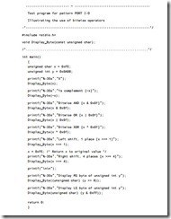
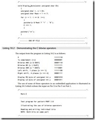
We can do this by making use of the bitwise AND, OR and ‘complement’ operators. These, and other, bitwise operators are not widely used by desktop developers. The various bitwise operators allow a number of data manipulations that are invaluable in embedded applications. Some examples of the use of these operators are given in Listing 10.2. Note that this file is written in ISO ‘C’ (’Desktop C’): it cannot be run on the Keil compiler.
The use of some of these operators in an embedded application is illustrated in Listing 10.3 which echoes the input on Pin X to Pin Y on Port 1.
Example: Displaying error codes in a scheduler
See CO – OPERA TIVE SCHEDULER [page 255], where error codes are displayed on a bank of LEDs connected to a port.
Example: Controlling an LCD
See LCD CHARACTER P ANEL [page 467], where control of individual port pins is used to send data to an LCD panel.
Further reading
Further information about the use of the ‘C’ bitwise operators will be found in any standard textbook on C programming.


