Multi-state switch
Context
● You are developing an embedded application using one or more members of the 8051 family of microcontrollers.
● The application has a time-triggered architecture, constructed using a scheduler.
● You are creating the user interface for your application.
Problem
How do you obtain the behaviour illustrated in Figure 19.13 from a single, push- button switch connected to the port pin of a microcontroller?
Background
—
Solution
Although – as discussed in ON – OFF SWITCH [page 414] – sustained switch depressions can sometimes be problematic, they can also form the basis of more complex switch- based interfaces and can allow us to turn this two-state input device into a three-state (or more) input device.
For example, if we have a real-time clock, we may have just two buttons (‘forward’ and ‘backward’) to set the time. To avoid this process becoming unduly tedious, we might decide that a brief depression of the ‘Forward’ button should slowly increment the displayed time, while a sustained depression (longer than, say, five seconds), should advance the display more rapidly.
To implement this type of behaviour, we might operate as follows:
● We keep track of the period of time over which the switch has been continually depressed.
● When the depression exceeds a threshold (call it Duration A), we treat this like a normal switch depression.
● When the depression exceeds a larger threshold (call it Duration B), we treat this as a sustained switch depression.
Note that further ‘levels’ can be added, but more than two (sometimes three) can be confusing to the user.
See the example that follows for complete implementation details.
Hardware resource implications
Creating a multi-state switch imposes very minor loads on CPU and memory resources.
Reliability and safety issues
The use of multi-state switches does not generally have reliability or safety implications.
Refer to SWITCH INTERF ACE ( SOFTW ARE ) [page 399] and SWITCH INTERF ACE
( HARDW ARE ) [page 410] for general discussions about the safety of switch interfaces.
Portability
This pattern may be adapted for use with other microcontrollers without difficulty.
Overall strengths and weaknesses
A cost-effective way of improving the usability of many applications.
Related patterns and alternative solutions
See ON – OFF SWITCH [page 414].
Example: Counter
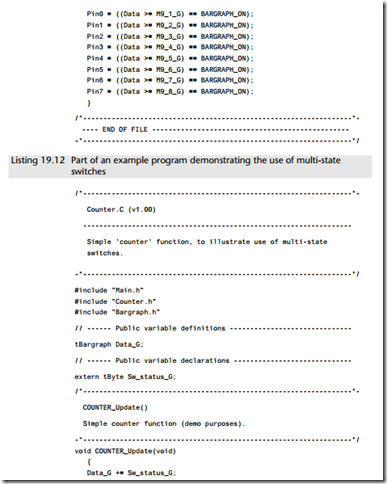
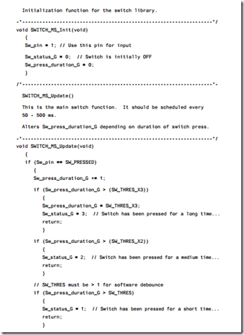
In this example, we demonstrate the key features of a multi-state switch by means of a counter that is incremented at a rate which depends on the switch-press duration (Listings 19.10 to 19.14).
The required hardware is illustrated in Figure 19.14.


