Pc link (rs-232)
Context
● You are developing an embedded application using one or more members of the 8051 family of microcontrollers.
● The application has a time-triggered architecture, constructed using a scheduler.
● You are creating the user interface for your application.
Problem
How do you link your embedded application to a desktop (or notebook or hand-held) PC using ‘RS-232’?
Background
This pattern is concerned with the use of what is commonly referred to as the RS-232 communication protocol, to transfer data between an 8051 microcontroller and some form of personal computer (PC, notebook or similar).
We provide some important background information on RS-232 in this section. We begin, however, by considering some important terminology used in the communica- tions area.
What are ‘simplex’, ‘half-duplex’ and ‘duplex’ serial communications?
In a simplex serial communication system, we typically require at least two wires (’signal’ and ‘ground’). Data transfer is only in one direction: for example, we might transfer data from a simple data-monitoring system to a PC using simplex data transfer.
In a half-duplex serial communication system we again (typically) require at least two wires. Here, data transfer can be in both directions. However, transmission can only be in one direction at a time. In a variation of the data-monitoring example, we might use a half-duplex communication strategy to allow us to send information to the embedded module (to set parameters, such as sampling rate). We might also, at other times, use the same link to download the data from the embedded board to a PC. In a full-duplex serial communication system, we typically require at least three wires (Signal A, Signal B, Ground). The line Signal A will carry data in one direction at
the same time that Signal B carries data in the other direction.
What is ‘RS-232’?
In 1997 the Telecommunications Industry Association released what is formally known as TIA-232 Version F, a serial communication protocol which has been
universally referred to as ‘RS-232’ since its first ‘Recommended Standard’ appeared in the 1960s. Similar standards (V.28) are published by the International Telecommunications Union (ITU) and by CCITT (Consultative Committee International Telegraph and Telephone).
The ‘RS-232’ standard includes details of:
● The protocol to be used for data transmission.
● The voltages to be used on the signal lines.
● The connectors to be used to link equipment together.
Overall, the standard is comprehensive and widely used, at data transfer rates of up to around 115 or 330 kbits / second (115 / 330 k baud). Data transfer can be over distances of 15 metres or more.
Note that RS-232 is a peer-to-peer communication standard. Unlike the multi-drop RS-485 standard (which we consider in Chapter 27), RS-232 is intended to link only two devices together.
Basic RS-232 protocol
RS-232 is a character-oriented protocol. That is, it is intended to be used to send single 8-bit blocks of data. To transmit a byte of data over an RS-232 link, we gener- ally encode the information as follows:
● We send a ‘Start’ bit.
● We send the data (8 bits).
● We send a ‘Stop’ bit (or bits).
We consider each of these stages here.
Quiescent state
When no data are being sent on an RS-232 ‘transmit’ line, the line is held at a Logic 1 level.
Start bit
To indicate the start of a data transmission we pull the ‘transmit’ line low.
Data
Data are often encoded in ASCII (American Standard Code for Information Interchange), in 7-bit form. The bits are sent least significant bit first. If we are send- ing 7-bit data, the eighth data bit is often used as a simple parity check bit and is transmitted in order to provide a rudimentary error detection facility on a character- by-character basis.
Note that none of the code presented here uses parity bits: we use all 8 bits for data transfer.
Stop bit(s)
The stop bits consist of a Logic 1 output. These can be 1 or, less commonly, 1G or 2 pulses wide.
Note that we will use a single stop bit in all code example.
Asynchronous data transmission and baud rates
RS-232 uses an asynchronous protocol. This means that no clock signal is sent with the data. Instead, both ends of the communication link have an internal clock, run- ning at the same rate. The data (in the case of RS-232, the ‘Start’ bit) is then used to synchronize the clocks, if necessary, to ensure successful data transfer.
RS-232 generally operates at one of a (restricted) range of baud rates. Typically these are: 75, 110, 300, 1,200, 2,400, 4,800, 9,600, 14,400, 19,200, 28,800, 33,600,
56,000, 115,000 and (rarely) 330,000 baud. Of these, 9,600 baud is a very ‘safe’ choice, as it is very widely supported.
RS-232 voltage levels
The threshold levels used by the receiver are +3V and -3V and the lines are inverted. The maximum voltage allowed is +/- 15V.
Note that these voltages cannot be obtained directly from the naked microcon- troller port pins: some form of interface hardware is required. For example, the Maxim Max232 and Max233 are popular and widely used line driver chips; we con- sider how to use such chips in ‘Solution’.
Flow control
RS-232 is often used with some form of flow control. This is a protocol, implemented through software or hardware, that allows a receiver of data to tell the transmitter to pause the dataflow. This might be necessary, for example, if we were sending data to a PC and the PC had filled a RAM buffer: the PC would then tell our embedded applica- tion to pause the data transfer until the buffer contents had been stored on disk.
Although hardware handshaking can be used, this requires extra signal lines. The most common flow control technique is ‘Xon / Xoff’ control. This requires a half- or full-duplex communication link, and can operate as follows:
1 Transmitter sends a byte of data.
2 The receiver is able to receive more data: it does nothing.
3 The transmitter sends another byte of data.
4 Steps 1–3 continue until the receiver cannot accept any more data: it then sends a ‘Control s’ (Xoff) character back to the transmitter.
5 The transmitter receives the ‘Xoff’ command and pauses the data transmission.
6 When the receiver node is ready for more data, it sends a ‘Control q’ (Xon) charac- ter to the transmitter.
7 The transmitter resumes the data transmission.
8 The process continues from Step 1.
Solution
In this section we consider how to implement an RS-232 link from an embedded 8051 microcontroller to a PC.
Transceiver hardware
As noted in ‘Background’, the voltages used in RS-232 communications are incompat- ible with the voltages used on the microcontroller itself. Therefore, you will require some form of voltage level conversion circuitry between the microcontroller board and the PC cable.
Usually the most cost-effective way of achieving this is to use a ‘transceiver’ (transmitter-receiver) chip created for this purpose. Of these, the Max232 (from Maxim) is frequently used; however, in new designs the more recent Max233 is a better choice as it requires fewer external components.
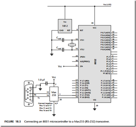
The required link to a Max233 is illustrated in Figure 18.1, which also shows the standard connections (9-pin D-type socket: ‘DB-9’) used for most recent designs.
Cable connections
To connect to the PC using the software presented here, you need a 3-wire cable.
Use DB-9 socket (‘female’) connector at the PC end and DB-9 plug (‘male’) connec- tor at the microcontroller end.
The required cable connections are a ‘straight through’ cable as described in Table 18.1.
The software architecture
Suppose we wish to transfer data to a PC at a standard 9,600 baud rate; that is, 9,600 bits per second. As we discussed in ‘Background’, transmitting each byte of data, plus stop and start bits, involves the transmission of ten bits of information (assuming a single stop bit is used). As a result, each byte takes approximately 1 ms to transmit.
This has important implications in all applications, not least those using a sched- uler. If, for example, we wish to send this information to the PC:
Current core temperature is 36.678 degrees
then the task sending these 42 characters will take more than 40 milliseconds to complete. This will frequently be an unacceptably long duration.
The most obvious way of solving this problem is to increase the baud rate; how- ever, this is not always possible and it does not solve the underlying problem.
A better solution is to write all data to a buffer in the microcontroller. The contents of this buffer will then be sent – usually one byte at a time – to the PC, using a regu- lar, scheduled task.
This solution is used in the code libraries presented in the following sections and included on the accompanying CD. The architecture is a good example of a MUL TI – ST AGE T ASK [page 317], and is frequently used in user-interface libraries: LCD CHARACTER P ANEL [page 467], for example, uses a very similar architecture.
Using the on-chip U(S)ART for RS-232 communications
Having decided on the basic architecture for the RS-232 library, we need to consider in more detail how the on-chip serial port is used.
This port is full duplex, meaning it can transmit and receive simultaneously. It is also receive buffered, meaning it can commence reception of a second byte before a previously received byte has been read from the receive register. (However, if the first byte still has not been read by the time reception of the second byte is complete, one of the bytes will be lost.)
The serial port can operate in four modes (one synchronous mode, three asynchro- nous modes). In this pattern, we are primarily interested in Mode 1. In this mode, 10 bits are transmitted (through TxD) or received (through RxD): a start bit (0), 8 data bits (lsb first), and a stop bit (1).
Note that the serial interface may also provide interrupt requests when transmis- sion or reception of a byte has been completed. However, for reasons discussed in Chapter 1, none of the code used in this pattern will generate interrupts.
Serial port registers
The serial port control and status register is the special function register SCON. This register contains the mode selection bits (and the serial port interrupt bits, TI and RI).
SBUF is the receive and transmit buffer of serial interface. Writing to SBUF loads the transmit register and initiates transmission. Reading out SBUF accesses a physi- cally separate receive register.
Baud rate generation
There are several different ways to generate the baud rate clock for the serial port depending on the mode in which it is operating.
As already noted, we are primarily concerned here with the use of the serial port in Mode 1. In this mode the baud rate is determined by the overflow rate of Timer 1 or Timer 2. For reasons discussed in Chapter 14, we assume that, if Timer 2 is available, it will usually be used to drive the scheduler. Therefore, we focus on the use of Timer 1 for baud rate generation.
The baud rate is determined by the Timer 1 overflow rate and the value of SMOD follows:
Thus, the required value of TH1 is 252.7447916667.
The nearest integer value is 253. This means that our actual baud rate will be approximately 10,417 baud – more than 8% higher than the required (9,600) rate.
Remember: This is an asynchronous protocol and relies for correct operation on the fact that both ends of the connection are working at the same baud rate. In practice, you can generally work with a difference in baud rates at both ends of the connection by up to 5%, but no more.
Despite the possible 5% margin, it is always good policy to get the baud rate as close as possible to the standard value because, in the field, there may be significant temperature variations between the oscillator in the PC and that in the embedded system. This will lead to a ‘drift’ in baud rates on PC and microcontroller, even if they were precisely the same to start with: as a result, if the baud rates were initially mismatched, then communication with the PC may fail completely during normal use. This type of ‘inexplicable fault’ has caused many developers sleepless nights (’I don’t understand it! It works fine in all the tests in the lab!’).
Note also that it is generally essential to use some form of crystal oscillator (rather than a ceramic resonator) when working with asynchronous serial links (such as RS-232, RS-485 or CAN): the ceramic resonator is not sufficiently stable for this purpose: see CR YST AL OSCILLA TOR [page 54] and CERAMIC RESONA TOR [page 64]for details.
Dealing with the 11.0592 MHz problem
In a scheduled application, using an 11.0592 MHz crystal oscillator is not ideal. 11.0592 MHz may translate into precise baud rates, but it is not ideal as a source of ‘ticks’ in the scheduler: in particular, it is impossible to produce precise 1 ms ticks from an 8051 device driven by an 11.0592 MHz crystal.
There are at least four solutions to this problem:
● The first solution is to use a 11.0592 MHz crystal and work with a 5 ms tick inter- val. Note that a 5 ms interval can be generated precisely at this crystal frequency, as demonstrated in the example on the CD.
● The second solution is to use Timer 2 to generate the baud rates. Timer 2 allows precise baud-rate generation at a wider range of oscillator frequencies than Timer 1; of course – in a single-processor system – this means that Timer 2 cannot simulta- neously be used to generate the scheduler ticks, and Timer 0 or Timer 1 will need to be used for this purpose.
● The third solution is to use the dedicated baud rate generator included on recent 8051 devices. These allow very standard baud rates to be generated even with – say
– 12 MHz crystals. In addition, use of a dedicated generator frees up the other timers for general-purpose use. Again, one of the libraries on the CD make use of internal baud rate generator.
● The fourth solution is to use two-microcontroller solution, and a shared-clock
scheduler. Figure 18.2 illustrates this approach.
PC software
We focus in this pattern on the software required on the microcontroller in order to transfer data to a PC. Clearly, however, we also need software on the PC itself.
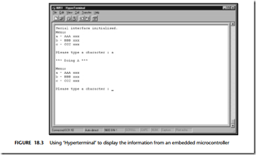
If your desktop computer is running Windows (95, 98, NT, 2000), then a simple but effective option is the ‘Hyperterminal’ application which is included with all of these operating systems. Figure 18.3 shows this application running one of the exam- ple applications.
While Hyperterminal (or similar terminal-emulator programs in other environ- ments) are useful, they are not suitable for all purposes.
If you need more specialized PC code for storing or analyzing data from your embedded application, you will probably need to write your own. Such programs lie beyond the scope of this book but Axelson (1998) is a good source of further informa- tion and useful code samples.
Hardware resource implications
The use of the PC link library described in this pattern has the following hardware resource implications:
● It uses the UART.
● It uses two port pins (P3.0, P3.1).
● It uses either a general-purpose timer or a specialized baud rate generator circuit.
Overall, however, it is the memory load that causes greatest difficulty, particularly in situations where only internal memory is available. The root of this difficulty is that fact that, as we discussed in ‘Solution’, the architecture used (to transmit data to the PC) is based on the use of a buffer to which the user writes as required; this buffer is then emptied, one character at a time, by a scheduled task.1
The buffer itself is very simple:
// The transmit buffer length
#define PC_LINK_TRAN_BUFFER_LENGTH 100
static tByte Tran_buffer[PC_LINK_TRAN_BUFFER_LENGTH];
If you run out of memory, there are several options:
● You can reduce the buffer size. This may mean that tasks in your applications must break down the data they send into smaller blocks. Typically, the main implication is that shorter strings must be used.
● You can increase the baud rate and adapt the code so that the scheduler sends more than one byte of data in every time the ‘update’ function is run.
● If using on-chip memory only, you can choose an 8051 device with additional on- chip RAM: for example, Dallas and Infineon produce a number of such devices. We discuss how to make use of this memory in OFF – CHIP DA T A MEMOR Y [page 94].
Reliability and safety issues
We consider the reliability and safety implications of RS-232 communications in this section.
What about printf()?
We do not generally recommend the use of standard library functions, such as
printf(), because:
● This function sends data immediately to the UART. As a result, the duration of the transmission is usually too long to be safely handled in a co-operatively scheduled application.
● Most implementations of printf() do not incorporate timeouts, making it possi- ble that use of this functions can ‘hang’ the whole application if errors occur.
If you are determined to use printf(), refer to Chapter 10 where a simple library using this function is presented.
General comments
The RS-232 protocol does not provide any adequate form of error checking: you need to carry this out manually. A simple approach is to send important data to the PC two (or more) times and compare the two (or more) versions: if there is a mismatch, have the data sent again. Clearly, this approach greatly increases the required communica- tion bandwidth.
Portability
The UART is part of the 8051 core: therefore if your application has a UART-based RS- 232 interface it will generally be portable. However, use of non-core features (like dedicated baud rate generators or more than one serial port) will dramatically reduce the porting opportunities.
Overall strengths and weaknesses
RS-232 support is part of the 8051 core: applications based on RS-232 are very portable.
At the PC end too, RS-232 is ubiquitous: every PC has one or more RS-232 ports.
Links can – with modern transceiver chips – be up to 30 m (100 ft) in length.
Because of the hardware support, RS-232 generally imposes a low software load.
RS-232 is a peer-to-peer protocol (unlike, for example, RS-485: see Chapter 27): you can only connect one microcontroller directly (simultaneously) to each PC.
RS-232 has little or no error checking at the hardware level (unlike, for exam- ple, CAN: see Chapter 28): if you want to be sure that the data you received at the PC are valid, you need to carry out checks in software.
Related patterns and alternative solutions
There are several related patterns and some alternative solutions. We discuss these here.
Selecting an oscillator or resonator
As already noted, it is generally essential to use some form of crystal oscillator (rather than a ceramic resonator) when working with asynchronous serial links: the ceramic resonator is not sufficiently stable for this purpose: see CR YST AL OSCILLA TOR [page 54] and CERAMIC RESONA TOR [ page 64] for details.
Multi-drop communications
If you wish to connect more than one microcontroller to a single PC, this is readily possible. Use a shared-clock scheduler (see SCI SCHEDULER ( DA T A ) [page 593] and SCC SCHEDULER [page 677]) to link the controllers together, and use a serial port on one of the boards to send the data to the PC, over an RS-232 link. If required, you can send data to multiple PCs in this way.
USB
RS-232 has been around since the 1960s. It is popular and effective, but has its limitations. Increasingly, PCs are being released with (additional) USB (universal serial bus) ports.
It is now becoming possible to use USB to transfer data between PCs and 8051 microcontrollers. For example, the Infineon C541 is an 8051 device with on-chip USB support. Note that this chip includes not just the USB controller, but also the driver as well: unlike RS-232, no external transceiver hardware is required (Figure 18.4).
Other USB-compatible 8051 devices are the EZ-USB range from Cypress Semiconductor,2 and the TUSB3200 from Texas Instruments.3
Note that for 8051 microcontrollers without USB support, an alternative you may wish to consider is the FT8U232AM USB UART chip from FTDI.4 As far as the 8051 is concerned, the USB UART appears to be an ordinary RS-232 transceiver.
Example: A PC Link library for the 8051/8052 (generic)
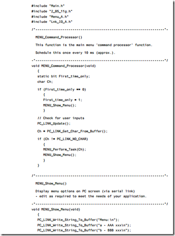
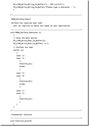
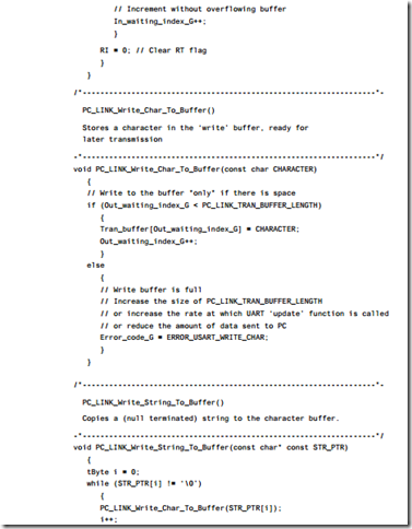
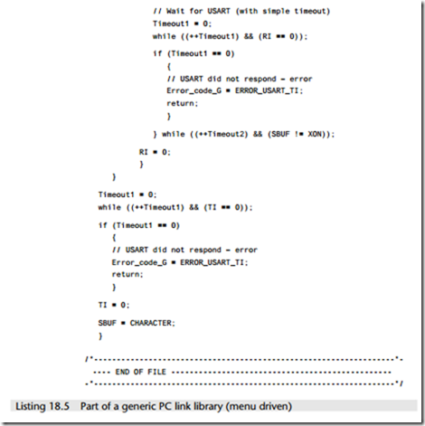
This example illustrates how to link a Standard 8051 device to a PC (listings 18.1 to 18.5). The software is menu driven in this example: the user is (via a terminal emula- tor on the PC) given the option of running one of three different tasks on the microcontroller (see Figure 18.5).
In this library, the scheduler is driven by Timer 2, and Timer 1 is used for baud rate generation.
As usual, all files for this example are included on the CD, in the directory associ- ated with this chapter.


