ROBUST RESET
Context
● You are developing an embedded application using one or more members of the 8051 family of microcontrollers.
● You are designing an appropriate hardware foundation for your application.
Problem
How do you create a very reliable reset circuit for your 8051 microcontroller?
Background
See RC RESET [page 68] for some background material on reset circuits.
Solution
As discussed in RC RESET [page 68], a key problem for the designers of reliable embed- ded systems is that power supplies are seldom ideal. For example, mains power supplies can take around 100 ms to reach their normal operating voltage when first switched on and may subsequently suffer from voltage variations, including brownouts, in part due to variations in the network load caused by other users of the mains supply. On the other hand, ‘1.5V’ primary cells (‘batteries’) often begin life with a voltage of up to 1.7V and decline to 0.9V or less as they are used.
Although careful design of your power supply can reduce these problems, it is often desirable to reduce the risks of system failure by maximizing the chances that your system will be reset correctly in the event of power supply problems. The robust reset circuits, notably from Dallas and Maxim, directly address this problem.
These useful devices perform two basic operations:
● When power is applied to a ‘cold’ system, they apply an appropriate (active high or active low) reset signal to the microcontroller for at least 100 ms to allow the oscil- lator (if used) and power supply to reach their operational state.
● If the supply voltage falls below a preset value during normal operation, the reset cycle will begin and will only end ~100 ms after the supply is restored to the normal value. This behaviour deals with both total power failures (long or short) and brownouts.
Overall, these devices are very effective and are cheap. Except where cost is the only concern, they are highly recommended.
Hardware resource implications
This pattern has no implications for CPU or memory usage.
Reliability and safety issues This form of reset circuit is, as a general rule, much safer than any RC-based equivalent.
Portability
The various robust reset chips are generally insensitive to power supply variations over a wide range: use of such devices therefore tends to make your design more portable and less dependent on a particular power supply. Most devices are available with both ‘active high’ and ‘active low’ versions and are therefore compatible with a wide range of 8051 chips.
Overall strengths and weaknesses
Robust reset provides reliable performance even with ‘slow’ power supplies and in the event of brownout.
More expensive than RC reset alternatives.
Related patterns and alternative solutions
RC RESET [page 68] offers a cheaper alternative where safety and reliability are much less important than product cost.
In addition, two further ways of obtaining reliable reset behaviour are now discussed.
On-chip reset circuits
Reset circuits are always a challenge with microcontroller-based systems and – now that small reset ICs are available – it seems surprising that this circuitry is not simply included in the microcontroller itself.
In fact, in more recent 8051s, such circuitry is included: see, for example, the Dallas DS87C520 / DS83C520 and the Philips 87LPC764. An example of a Dallas 87C520 circuit using internal reset components is given in the following section.
Microcontroller / microprocessor supervisor ICs
The robust reset circuits discussed here are simple, economical reset options. However, in some applications, we require other external facilities too. Maxim, in particular, have developed a range of different ‘microcontroller supervisor’ ICs that include not only the equivalent of ‘robust reset’ circuits, but also have various combinations of additional facilities, such as watchdog timers and even RS-232 transceivers. Three examples of such devices are summarized here: consult the Maxim WWW site11 for further details.
11. www.maxim-ic.com
● Max6330/1: Reset control, plus 3V / 3.3V / 5V shunt regulator. This allows a single, inexpensive IC chip to be used for both the power supply regulation and reset circuit.
● Max819: Reset control plus watchdog, plus battery switchover.
● Max3320: Reset control, plus RS-232 transceiver.
In addition, the ‘1232’ power monitor (available in various versions from both Dallas and Maxim) combines ROBUST RESET behaviour with a watchdog timer: as we see in Chapter 12, this is a very useful combination in many applications.
Example: Using the Dallas DS1812 ‘Econoreset’ with the 8051 family
Please refer to Chapter 26, Figure 26.10, for one of many examples in this book that use the DS1812 robust reset with the Standard 8051 device.
Example: Using Dallas ‘Econoresets’ with the Infineon C515C-8E
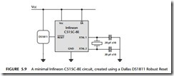
A minimal Infineon C515C-8E circuit, created using a Dallas DS1811 robust reset, is shown in Figure 5.9.
Example: Using the Max810M with the Infineon C501-1E
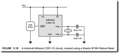
A minimal Infineon C501-1E circuit, created using a Maxim 810M robust reset, is shown in Figure 5.10.
Example: Minimal Dallas circuit using on-chip reset circuit
As noted earlier, some more recent 8051 devices have on-chip reset circuitry.
As an example, we will consider the DS87C520 (see Figure 5.11), whose circuitry operates as follows. While powering up, the internal monitor circuit maintains a reset state until Vcc rises above the ‘reset’ level. Once above this level, the monitor enables the oscillator input and counts 65,536 clock cycles, before leaving the reset state. This power-on reset (POR) interval allows time for the both the power supply and oscilla- tor to stabilize. In addition, if the supply voltage drops during normal operation, power monitor will generate and hold a reset automatically.
Note that this solution works with many of the Dallas ‘high speed’ and ‘ultra high speed’ devices, including the 80C320, 80C323, 83C520, 87C520, 87C530, 87C550 and 89C420.


