INSTRUCTION SET
The arithmetic coprocessor executes over 68 different instructions. Whenever a coprocessor instruction references memory, the microprocessor automatically generates the memory address for the instruction. The coprocessor uses the data bus for data transfers during coprocessor instructions and the microprocessor uses it during normal instructions. Also note that the 80287 uses the Intel-reserved I/O ports 00F8H–00FFH for communications between the coprocessor and the microprocessor (even though the coprocessor only uses ports 00FCH–00FFH). These ports are used mainly for the FSTSW AX instruction. The 80387–Core2 use I/O ports 800000F8H–800000FFH for these communications.
This section of the text describes the function of each instruction and lists its assembly language form. Because the coprocessor uses the microprocessor memory-addressing modes, not all forms of each instruction are illustrated. Each time that the assembler encounters a coprocessor mnemonic opcode, it converts it into a machine language ESC instruction. The ESC instruction represents an opcode to the coprocessor.
Data Transfer Instructions
There are three basic data transfers: floating-point, signed integer, and BCD. The only time that data ever appear in the signed integer or BCD form is in the memory. Inside the coprocessor, data are always stored as an 80-bit extended-precision floating-point number.
Floating-Point Data Transfers. There are four traditional floating-point data transfer instructions in the coprocessor instruction set: FLD (load real), FST (store real), FSTP (store real and pop), and FXCH (exchange). A new instruction is added to the Pentium Pro through Core2 called a conditional floating-point move instruction that uses the opcode FCMOV with a floating-point condition.
The FLD instruction loads floating-point memory data to the top of the internal stack, referred to as ST (stack top). This instruction stores the data on the top of the stack and then decrements the stack pointer by 1. Data loaded to the top of the stack are from any memory location or from another coprocessor register. For example, an FLD ST(2) instruction copies the con- tents of register 2 to the stack top, which is ST. The top of the stack is register 0 when the coprocessor is reset or initialized. Another example is the FLD DATA7 instruction, which copies the contents of memory location DATA 7 to the top of the stack. The size of the transfer is auto- matically determined by the assembler through the directives DD or REAL4 for single-precision, DQ or REAL 8 for double-precision, and DT or REAL10 for extended temporary-precision.
The FST instruction stores a copy of the top of the stack into the memory location or coprocessor register indicated by the operand. At the time of storage, the internal, extended temporary-precision floating-point number is rounded to the size of the floating-point number indicated by the control register.
The FSTP (floating-point store and pop) instruction stores a copy of the top of the stack into memory or any coprocessor register, and then pops the data from the top of the stack. You might think of FST as a copy instruction and FSTP as a removal instruction.
The FXCH instruction exchanges the register indicated by the operand with the top of the stack. For example, the FXCH ST(2) instruction exchanges the top of the stack with register 2.
Integer Data Transfer Instructions. The coprocessor supports three integer data transfer instructions: FILD (load integer), FIST (store integer), and FISTP (store integer and pop). These three instructions function as did FLD, FST, and FSTP, except that the data transferred are integer data. The coprocessor automatically converts the internal extended temporary-precision floating-point data to integer data. The size of the data is determined by the way that the label is defined with DW, DD, or DQ in the assembly language program.
BCD Data Transfer Instructions. Two instructions load or store BCD signed-integer data. The FBLD instruction loads the top of the stack with BCD memory data, and the FBSTP stores the top of the stack and does a pop.
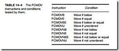
The Pentium Pro through Pentium 4 FCMOV Instruction. The Pentium Pro–Pentium 4 micro- processors contain a new instruction called FCMOV, which also contains a condition. If the condition is true, the FCMOV instruction copies the source to the destination. The conditions tested by FCMOV and the opcodes used with FCMOV appear in Table 14–4. Notice that these conditions check for either an ordered or unordered condition. The testing for NAN and denormalized numbers are not checked with FCMOV.
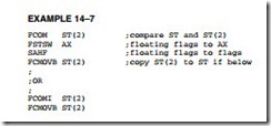
Example 14–7 shows how the FCMOVB (move if below) instruction is used to copy the contents of ST(2) to the stack top (ST) if the contents of ST(2) is below ST. Notice that the FCOM instruction must be used to perform the compare and the contents of the status register must still be copied to the flags for this instruction to function. More about the FCMOV instruction appears with the FCOMI instruction, which is also new to the Pentium Pro through the Core2 microprocessors.
Arithmetic Instructions
Arithmetic instructions for the coprocessor include addition, subtraction, multiplication, division, and calculating square roots. The arithmetic-related instructions are scaling, rounding, absolute value, and changing the sign.
Table 14–5 shows the basic addressing modes allowed for the arithmetic operations. Each addressing mode is shown with an example using the FADD (real addition) instruction. All arithmetic operations are floating-point, except some cases in which memory data are referenced as an operand.
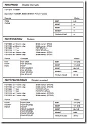
The classic stack form of addressing operand data (stack addressing) uses the top of the stack as the source operand and the next to the top of the stack as the destination operand. Afterward, a pop removes the source datum from the stack and only the result in the destination register remains at the top of the stack. To use this addressing mode, the instruction is placed in the program without any operands such as FADD or FSUB. The FADD instruction adds ST to ST(1) and stores the answer at the top of the stack; it also removes the original two data from the stack by popping. Note carefully that FSUB subtracts ST from ST(1) and leaves the difference at ST. Therefore, a reverse subtraction (FSUBR) subtracts ST(1) from ST and leaves the difference at ST. (Note that an error exists in Intel documentation, including the Pentium data book, which describes the operation of some reverse instructions.) Another use for reverse operations is for finding a reciprocal (1/X). This is accomplished, if X is at the top of the stack, by loading a 1.0 to ST, followed by the FDIVR instruction. The FDIVR instruction divides ST(1) into ST or X into 1 and leaves the reciprocal (1/X) at ST.
The register-addressing mode uses ST for the top of the stack and ST(n) for another loca- tion, where n is the register number. With this form, one operand must be ST and the other is ST(n). Note that to double the top of the stack, the FADD ST,ST(0) instruction is used where ST(0) also addresses the top of the stack. One of the two operands in the register-addressing mode must be ST, while the other must be in the form ST(n), where n is a stack register 0–7. For many instructions, either ST or ST(n) can be the destination. It is fairly important that the top of the stack be ST(0). This is accomplished by resetting or initializing the coprocessor before using it in a program. Another example of register-addressing is FADD ST(1),ST where the contents of ST are added to ST(1) and the result is placed in ST(1).
The top of the stack is always used as the destination for the memory-addressing mode because the coprocessor is a stack-oriented machine. For example, the FADD DATA instruction adds the real number contents of memory location DATA to the top of the stack.
Arithmetic Operations. The letter P in an opcode specifies a register pop after the operation (FADDP compared to FADD). The letter R in an opcode (subtraction and division only) indicates reverse mode. The reverse mode is useful for memory data because memory data normally subtract from the top of the stack. A reversed subtract instruction subtracts the top of the stack from memory and stores the result in the top of the stack. For example, if the top of the stack contains a 10 and memory location DATAl contains a 1, the FSUB DATA1 instruction results in a +9 on the stack top, and the FSUBR instruction results in a –9. Another example is FSUBR ST,ST(1), which will subtract ST from ST(1) and store the result on ST. A variant is FSUBR ST(1),ST, which will subtract ST(1) from ST and store the result on ST(1).
The letter I as a second letter in an opcode indicates that the memory operand is an integer. For example, the FADD DATA instruction is a floating-point addition, while the FIADD DATA is an integer addition that adds the integer at memory location DATA to the floating- point number at the top of the stack. The same rules apply to FADD, FSUB, FMUL, and FDIV instructions.
Arithmetic-Related Operations. Other operations that are arithmetic in nature include FSQRT (square root), FSCALE (scale a number), FPREM/FPREM1 (find partial remainder), FRNDINT (round to integer), FXTRACT (extract exponent and significand), FABS (find absolute value), and FCHG (change sign). These instructions and the functions that they per- form follow:
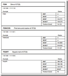
FSQRT Finds the square root of the top of the stack and leaves the resultant square root at the top of the stack. An invalid error occurs for the square root of a negative number. For this reason, the IE bit of the status register should be tested whenever an invalid result can occur. The IE bit can be tested by loading the status register to AX with the FSTSW AX instruction, followed by TEST AX,1 to test the IE status bit.
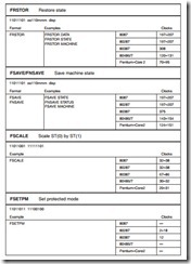
FSCALE Adds the contents of ST(1) (interpreted as an integer) to the exponent at the top of the stack. FSCALE multiplies or divides rapidly by powers of two. The value in ST(1) must be between 2–15 and 2+15.
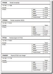
FPREM/FPREM1 Performs modulo division of ST by ST(1). The resultant remainder is found in the top of the stack and has the same sign as the original div dend. Note that a modulo division results in a remainder without a quotient. Note also that FPREM is supported for the 8086 and 80287, and FPREM1 should be used in newer coprocessors.
FRNDINT Rounds the top of the stack to an integer.
FXTRACT Decomposes the number at the top of the stack into two separate parts that represent the value of the unbiased exponent and the value of the significand. The extracted significand is found at the top of the stack and the unbiased exponent at ST(1). This instruction is often used to convert a floating-point number into a form that can be printed as a mixed number.
FABS Changes the sign of the top of the stack to positive.
FCHS Changes the sign from positive to negative or negative to positive.
Comparison Instructions
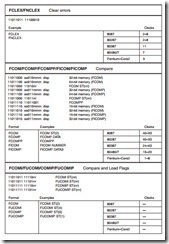
The comparison instructions all examine data at the top of the stack in relation to another element and return the result of the comparison in the status register condition code bits C3–C0. Comparisons that are allowed by the coprocessor are FCOM (floating-point compare), FCOMP (floating-point compare with a pop), FCOMPP (floating-point compare with two pops), FICOM (integer compare), FICOMP (integer compare and pop), FSTS (test), and FXAM (examine). New with the introduction of the Pentium Pro is the floating compare and move
results to flags or FCOMI instruction. Following is a list of these instructions with a description of their functions:
FCOM Compares the floating-point data at the top of the stack with an operand, which may be any register or any memory operand. If the operand is not coded with the instruction, the next stack element ST(1) is compared with the stack top ST.
FCOMP/FCOMPP Both instructions perform as FCOM, but they also pop one or two data from the stack.
FICOM/FICOMP The top of the stack is compared with the integer stored at a memory operand. In addition to the compare, FICOMP also pops the top of the stack.
FTST Tests the contents of the top of the stack against a zero. The result of the comparison is coded in the status register condition code bits, as illustrated in Table 14–2 with the status register. Also, refer to Table 14–3 for a way of using SAHF and the conditional jump instruction with FTST.
FXAM Examines the stack top and modifies the condition code bits to indi- cate whether the contents are positive, negative, normalized, and so on. Refer to the status register in Table 14–2.
FCOMI/FUCOMI New to the Pentium Pro through the Pentium 4, this instruction com- pares in exactly the same manner as the FCOM instruction, with one additional feature: It moves the floating-point flags into the flag regis- ter, just as the FNSTSW AX and SAHF instructions do in Example 14–8. Intel has combined the FCOM, FNSTSW AX, and SAHF instructions to form FCOMI. Also available is the unordered compare or FUCOMI. Each is also available with a pop by appending the opcode with a P.
Transcendental Operations
The transcendental instructions include FPT AN (partial tangent), FPATAN (partial arctangent), FSIN (sine), FCOS (cosine), FSINCOS (sine and cosine), F2XM1 (2X – 1), FYL2X (Y log2 X), and FYL2XP1 [Y log2 (X + 1)]. A list of these operations follows with a description of each transcendental operation:
FPTAN Finds the partial tangent of Y/X = tan θ. The value of θ is at the top of the stack. It must be between 0 and n/4 radians for the 8087 and 80287, and must be less than 263 for the 80387, 80486/7, and Pentium–Core2 microprocessors. The result is a ratio found as ST = X and ST(1) = Y. If the value is out- side of the allowable range, an invalid error occurs, as indicated by the status register IE bit. Also note that ST(7) must be empty for this instruction to function properly.
FPATAN Finds the partial arctangent as θ = ARCTAN X/Y. The value of X is at the top of the stack and Y is at ST(1). The values of X and Y must be as follows: 0 ≤ Y < X <∞. The instruction pops the stack and leaves θ in radians at the top of the stack.
F2XM1 Finds the function 2X – 1. The value of X is taken from the top of the stack and the result is returned to the top of the stack. To obtain 2X add one to the
result at the top of the stack. The value of X must be in the range of -1 and +1. The F2XM1 instruction is used to derive the functions listed in Table 14–6. Note that the constants log2 10 and log2 ε are built in as standard values for the coprocessor.
FSIN/FCOS Finds the sine or cosine of the argument located in ST expressed in radians (360° = 2π radians), with the result found in ST. The values of ST must be less than 263.
FSINCOS Finds the sine and cosine of ST, expressed in radians, and leaves the results as ST = sine and ST(1) = cosine. As with FSIN or FCOS, the initial value of ST must be less than 263.
FYL2X Finds Y log2 X. The value X is taken from the stack top, and Y is taken from ST(1). The result is found at the top of the stack after a pop. The value of X must range between 0 and ∞, and the value of Y must be between -∞ and +∞. A logarithm with any positive base (b) is found by the equation LOGb X =
(LOG2 b)-1 × LOG2 X.
FYL2P1 Finds Y log2 (X + 1). The value of X is taken from the stack top and Y is taken from ST(1). The result is found at the top of the stack after a pop. The
value of X must range between 0 and 1 –
between -∞ and +∞.
2>2 and the value of Y must be
Constant Operations
The coprocessor instruction set includes opcodes that return constants to the top of the stack. A list of these instructions appears in Table 14–7.
Coprocessor Control Instructions
The coprocessor has control instructions for initialization, exception handling, and task switching. The control instructions have two forms. For example, FINIT initializes the coprocessor, as does FNINIT. The difference is that FNINIT does not cause any wait states, while FINIT does
cause waits. The microprocessor waits for the FINIT instruction by testing the BUSY pin on the coprocessor. All control instructions have these two forms. Following is a list of each control instruction with its function:
FINIT/FNINIT Performs a reset (initialize) operation on the arithmetic coprocessor (see Table 14–8 for the reset conditions). The coprocessor operates with a closure of projective (unsigned infinity), rounds to the nearest or even, and uses extended-precision when reset or initialized. It also sets register 0 as the top of the stack.
FSETPM Changes the addressing mode of the coprocessor to the protected- addressing mode. This mode is used when the microprocessor is also operated in the protected mode. As with the microprocessor, protected mode can only be exited by a hardware reset or, in the case of the 80386 through the Pentium 4, with a change to the control register.
FLDCW Loads the control register with the word addressed by the operand.
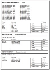
FSTCW Stores the control register into the word-sized memory operand.
FSTSW AX Copies the contents of the control register to the AX register. This instruction is not available to the 8087 coprocessor.
FCLEX Clears the error flags in the status register and also the busy flag.
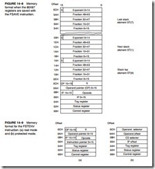
FSAVE Writes the entire state of the machine to memory. Figure 14–8 shows the memory layout for this instruction.
FRSTOR Restores the state of the machine from memory. This instruction is used to restore the information saved by FSAVE.
FSTENV Stores the environment of the coprocessor, as shown in Figure 14–9.
FLDENV Reloads the environment saved by FSTENV.
FINCSP Increments the stack pointer.
FDECSP Decrements the stack pointer.
FFREE Frees a register by changing the destination register’s tag to empty. It does not affect the contents of the register.
FNOP Floating-point coprocessor NOP.
FWAIT Causes the microprocessor to wait for the coprocessor to finish an operation. FWAIT should be used before the microprocessor accesses memory data that are affected by the coprocessor.
Coprocessor Instructions
Although the microprocessor circuitry has not been discussed, the instruction sets of these coprocessors and their differences from the other versions of the coprocessor can be discussed. These newer coprocessors contain the same basic instructions provided by the earlier versions, with a few additional instructions.
The 80387, 80486, 80487SX, and Pentium through the Core2 contain the following additional instructions: FCOS (cosine), FPREM1 (partial remainder), FSIN (sine), FSINCOS (sine and
cosine), and FUCOM/FUCOMP/FUCOMPP (unordered compare). The sine and cosine instructions are the most significant addition to the instruction set. In the earlier versions of the coprocessor, the sine and cosine is calculated from the tangent. The Pentium Pro through the Core2 contain two new floating-point instructions: FCMOV (a conditional move) and FCOMI (a compare and move to flags).
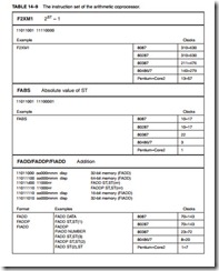
Table 14–9 lists the instruction sets for all versions of the coprocessor. It also lists the number of clocking periods required to execute each instruction. Execution times are listed for the 8087, 80287, 80387, 80486, 80487, and Core2. (The timings for the Pentium through the Pentium 4 are the same because the coprocessor is identical in each of these microprocessors.) To determine the execution time of an instruction, the clock time is multiplied times the listed execution time. The FADD instruction requires 70–143 clocks for the 80287. Suppose that an 8 MHz clock is used with the 80287. The clocking period is 1/8 MHz, or 125 ns. The FADD instruction requires between 8.75 μs and 17.875 μs to execute. Using a 33 MHz (33 ns) 80486DX2, this instruction requires between 0.264 μs and 0.66 μs to execute. On the Pentium the FADD instruction requires from 1–7 clocks, so if operated at 133 MHz (7.52 ns), the FADD requires between 0.00752 μs and 0.05264 μs. The Pentium Pro through the Core2 are even faster than the Pentium. For example, in a 3 GHz Pentium 4, which has a clock period of 0.333 ns, the FADD instruction requires between 0.333 ns and 2.333 ns to execute.
Table 14–9 uses some shorthand notations to represent the displacement that may or may not be required for an instruction that uses a memory-addressing mode. It also uses the abbrevi- ation mmm to represent a register/memory addressing mode and uses rrr to represent one of the floating-point coprocessor registers ST(0)–ST(7). The d (destination) bit that appears in some instruction opcodes defines the direction of the data flow, as in FADD ST,ST(2) or FADD ST(2),ST. The d bit is a logic 0 for flow toward ST, as in FADD ST,ST(2), where ST holds the sum after the addition; and a logic 1 for FADD ST(2),ST, where ST(2) holds the sum.
Also note that some instructions allow a choice of whether a wait is inserted. For example, the FSTSW AX instruction copies the status register into AX. The FNSTSW AX instruction also copies the status register to AX, but without a wait.
