MOVING TO PROTECTED MODE
In order to change the operation of the 80386 from the real mode to the protected mode, several steps must be followed. Real mode operation is accessed after a hardware reset or by changing the PE bit to a logic 0 in CR0. Protected mode is accessed by placing a logic 1 into the PE bit of CR0; before this is done, however, some other things must be initialized. The following steps accomplish the switch from the real mode to the protected mode:
1. Initialize the interrupt descriptor table so that it contains valid interrupt gates for at least the first 32 interrupt type numbers. The IDT may (and often does) contain up to 256 eight-byte interrupt gates defining all 256 interrupt types.
2. Initialize the global descriptor table (GDT) so that it contains a null descriptor at descriptor 0 and valid descriptors for at least one code, one stack, and one data segment.
3. Switch to protected mode by setting the PE bit in CR0.
4. Perform an intersegment (far) JMP to flush the internal instruction queue.
5. Load all the data selectors (segment registers) with their initial selector values.
6. The 80386 is now operating in the protected mode, using the segment descriptors that are defined in GDT and IDT.
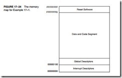
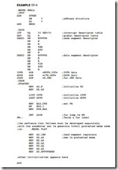
Figure 17–24 shows the protected system memory map set up by following steps 1–6. The software for this task is listed in Example 17–1. This system contains one data segment descriptor and one code segment descriptor with each segment set to 4G bytes in length. This is the sim- plest protected mode system possible (called the flat model): loading all the segment registers, except code, with the same data segment descriptor from the GDT. The privilege level is initial- ized to 00, the highest level. This system is most often used where one user has access to the microprocessor and requires the entire memory space. This program is designed for use in a sys- tem that does not use DOS or does not shell from Windows to DOS. Later in this section, we show how to go to protected mode in a DOS environment. (Please note that the software in Example 17–1 is designed for a stand-alone system such as the 80386EX embedded micro- processor, and not for use in the PC.)
Example 17–1 does not store any interrupt vectors into the interrupt descriptor table, because none are used in the example. If interrupt vectors are used, then software must be included to load the addresses of the interrupt service procedures into the IDT. The software must be generated as two separate parts that are then connected together and burned on a ROM. The first part is written as shown in the real mode and the second part (see comment in listing) with the assembler set to generate protected mode code using the 32-bit flat model. This software will not function on a personal computer because it is written to function on an embedded sys- tem. The code must be converted to a binary file using EXE2BIN after it is assembled and before burning to a ROM.
In more complex systems (very unlikely to appear in embedded systems), the steps required to initialize the system in the protected mode are more involved. For complex systems that are often multiuser systems, the registers are loaded by using the task state segment (TSS). The steps required to place the 80386 into protected mode operation for a more complex system using a task switch follow:
1. Initialize the interrupt descriptor table so that it refers to valid interrupt descriptors with at least 32 descriptors in the IDT.
2. Initialize the global descriptor table so that it contains a task state segment (TSS) descriptor, and the initial code and data segments required for the initial task.
3. Initialize the task register (TR) so that it points to a TSS.
4. Switch to protected mode by using an intersegment (far) jump to flush the internal instruction queue. This loads the TR with the current TSS selector and initial task.
5. The 80386 is now operating in the protected mode under control of the first task.
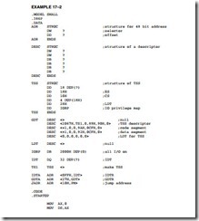
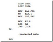
Example 17–2 illustrates the software required to initialize the system and switch to protected mode by using a task switch. The initial system task operates at the highest level of protection (00) and controls the entire operating environment for the 80386. In many cases, it is used to boot (load) software that allows many users to access the system in a multiuser environment. As with Example 17–2 this software will not function on a personal computer and is designed to function only on an embedded system.
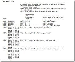
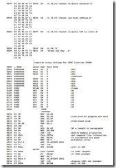
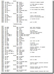
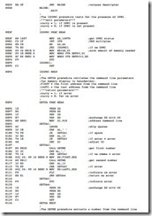
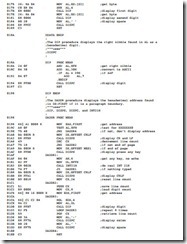
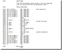
Neither Example 17–1 nor Example 17–2 is written to function in the personal computer environment. The personal computer environment requires the use of either the VCPI (virtual control program interface) driver provided by the HIMEM.SYS driver in DOS or the DPMI (DOS protected mode interface) driver provided by Windows when shelling to DOS. Example 17–3 shows how to switch to protected mode using DPMI and then display the contents of any area of memory. This includes memory in the extended memory area or anywhere else. This DOS application allows the contents of any memory location to be displayed in hexadecimal for- mat on the monitor, including locations above the first 1M byte of the memory system.
You might notice that the DOS INT 21H function call must be treated differently when operating in the protected mode. The procedure that calls a DOS INT 21H is at the end of Example 17–3. Because this is extremely long and time consuming, we have tended to move away from using the DOS interrupts from a Windows application. The best way to develop software for Windows is through the use of C/C++ with the inclusion of assembly language procedures for arduous tasks
