INTERRUPT EXAMPLES
This section of the text presents a real-time clock and an interrupt-processed keyboard as examples of interrupt applications. A real-time (RTC) clock keeps time in real time—that is, in hours and minutes. It is also used for precision time delays. The example illustrated here keeps time in Modem Control Register Modem Status Register
hours, minutes, seconds, and l/60 second, using four memory locations to hold the BCD time of day. The interrupt-processed keyboard uses a periodic interrupt to scan through the keys of the keyboard.
Real-Time Clock
Figure 12–26 illustrates a simple circuit that uses the 60 Hz AC power line to generate a periodic interrupt request signal for the NMI interrupt input pin. Although we are using a signal from the AC power line, which varies slightly in frequency from time to time, it is accurate over a period of time as mandated by the Federal Trade Commission (FTC).
The circuit uses a signal from the 120 V AC power line that is conditioned by a Schmitt trigger inverter before it is applied to the NMI interrupt input. Note that you must make certain that the power line ground is connected to the system ground in this schematic. The power line neutral (white wire) connection is the wide flat pin on the power line. The narrow flat pin is the hot (black wire) side or 120 V AC side of the line.
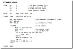
The software for the real-time clock contains an interrupt service procedure that is called 60 times per second and a procedure that updates the count located in four memory locations. Example 12–14 lists both procedures, along with the four bytes of memory used to hold the BCD time of day. The memory locations for the TIME are stored somewhere in the system memory at the segment address (SEGMENT) and at the offset address TIME, which is first loaded in the TIMEP procedure. The lookup table (LOOK) for the modulus or each counter is stored in the code segment with the procedure.
Another way to handle time is to use a single counter to store the time in memory and then determine the actual time with software. For example, the time can be stored in one single 32-bit counter (there are 5,184,000 1/60 sec in a day). In a counter such as this, a count of 0 is 12:00:00:00 AM and a count of 5,183,999 is 11:59:59:59 PM. Example 12–15 shows the interrupt procedure for this type of RTC, which requires the least of amount of time to execute.
Software to convert the count in the modulus 5,184,000 counter into hours, minutes, and seconds appears in Example 12–16. The procedure returns with the number of hours (0–23) in BL, number of minutes in BH, and number of seconds in AL. No attempt was made to retrieve the 1/60 second count.
Suppose a time delay is needed. Time delays can be achieved using the RTC in Example 12–15 for any amount from 1/60 of a second to 24 hours. Example 12–17 shows a procedure that uses the RTC to perform time delays of the number of seconds passed to the procedure in the EAX register. This can be 1 second to an entire day’s worth of seconds. It has an accuracy to within 1/60 second, the resolution of the RTC.
Interrupt-Processed Keyboard
The interrupt-processed keyboard scans through the keys on a keyboard through a periodic interrupt. Each time the interrupt occurs, the interrupt-service procedure tests for a key or debounces the key. Once a valid key is detected, the interrupt service procedure stores the key code into a keyboard queue for later reading by the system. The basis for this system is a periodic interrupt that can be caused by a timer, RTC, or other device in the system. Note that most systems already have a periodic interrupt for the real-time clock. In this example, we assume the interrupt calls the interrupt service procedure every 10 ms or, if the RTC is used with a 60 Hz clock, every 16.7 ms.
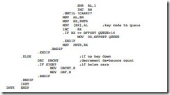
Figure 12–27 shows the keyboard interfaced to an 82C55. It does not show the timer or other circuitry required to call the interrupt once in every 10 ms or 16.7 ms. (Not shown in the software is programming of the 82C55.) The 82C55 must be programmed so that port A is an input port, port B is an output port, and the initialization software must store 00H at port B. This interfaces uses memory that is stored in the code segment for a queue and a few bytes that keep track of the keyboard scanning. Example 12–18 lists the interrupt service procedure for the keyboard.
The keyboard-interrupt finds the key and stores the key code in the queue. The code stored in the queue is a raw code that does not indicate the key number. For example, the key code for the 1-key is 00H, the key code for the 4-key is 01H, and so on. There is no provision for a queue overflow in this software. It could be added, but in almost all cases it is difficult to out-type a 16-byte queue.
Example 12–19 illustrates a procedure that removes data from the keyboard queue. This procedure is not interrupt-driven and is called only when information from the keyboard is needed in a program. Example 12–20 shows the caller software for the key procedure.


