DISK MEMORY SYSTEMS
Disk memory is used to store long-term data. Many types of disk storage systems are available today and they use magnetic media, except the optical disk memory that stores data on a plastic disk. Optical disk memory is either a CD-ROM (compact disk/read only memory) that is read, but never written, or a WORM (write once/read mostly) that is read most of the time, but can be written once by a laser beam. Also becoming available is optical disk memory that can be read and written many times, but there is still a limitation on the number of write operations allowed. The latest optical disk technology is called DVD (digital-versatile disk). The DVD (8.5G) is also available in high-resolution versions for video and data storage as Blray (50G) or HD-DVD (30G). This section of the chapter provides an introduction to disk memory systems so that they may be used with computer systems. It also provides details of their operation.
Floppy Disk Memory
Once the most common and the most basic form of disk memory was the floppy, or flexible disk. Today the floppy is beginning to vanish and may completely disappear shortly in favor of the USB pen drive. The floppy disk magnetic recording media have been made available in three sizes: the 8" standard, 51/4" mini-floppy, and the 31/2" micro-floppy. Today, the 8" standard version and 51/4" mini-floppy have all but disappeared, giving way to the micro-floppy disks and more recently pen drives. The 8" disk is too large and difficult to handle and stockpile. To solve this problem, industry developed the 51/4" mini-floppy disk. Today, the micro-floppy disk has just about replaced the mini-floppy in newer systems because of its reduced size, ease of storage, and durability. Even so, systems are still marketed with the micro-floppy disk drives.
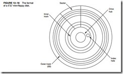
All disks and even the pen drives have several things in common. They are all organized so that data are stored in tracks. A track is a concentric ring of data that is stored on a surface of a disk. Figure 13–18 illustrates the surface of a 51/4" mini-floppy disk, showing a track that is divided into sectors. A sector is a common subdivision of a track that is designed to hold a reasonable amount of data. In many systems, a sector holds either 512 or 1024 bytes of data. The size of a sector can vary from 128 bytes to the length of one entire track.
Notice in Figure 13–18 that there is a hole through the disk that is labeled an index hole. The index hole is designed so that the electronic system that reads the disk can find the beginning of a track and its first sector (00). Tracks are numbered from track 00, the outermost track, in increasing value toward the center or innermost track. Sectors are often numbered from sector 00 on the outermost track to whatever value is required to reach the innermost track and its last sector.
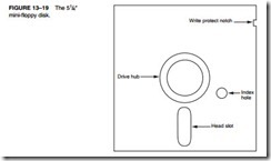
The 5 1/4" Mini-floppy Disk. Today, the 51/4" floppy is very difficult to find and is used only with older microcomputer systems. Figure 13–19 illustrates this mini-floppy disk. The floppy disk is rotated at 300 RPM inside its semi-rigid plastic jacket. The head mechanism in a floppy disk drive makes physical contact with the surface of the disk, which eventually causes wear and damage to the disk.
Most mini-floppy disks are double-sided. This means that data are written on both the top and bottom surfaces of the disk. A set of tracks called a cylinder consists of one top and one bottom track. Cylinder 00, for example, consists of the outermost top and bottom tracks.
Floppy disk data are stored in the double-density format, which uses a recording technique called MFM (modified frequency modulation) to store the information. Double-density, double-sided (DSDD) disks are normally organized with 40 tracks of data on each side of the
disk. A double-density disk track is typically divided into nine sectors, with each sector containing 512 bytes of information. This means that the total capacity of a double-density, double-sided disk is 40 tracks per side × 2 sides × 9 sectors per track × 512 bytes per sector, or 368,640 (360K) bytes of information.
Also common are high-density (HD) mini-floppy disks. A high-density mini-floppy disk contains 80 tracks of information per side, with eight sectors per track. Each sector contains 1024 bytes of information. This gives the 51/4" high-density, mini-floppy disk a total capacity of 80 tracks per side × 2 sides × 15 sectors per track × 512 bytes per sector, or 1,228,800 (approximately 1.2 M) bytes of information.
The magnetic recording technique used to store data on the surface of the disk is called non-return to zero (NRZ) recording. With NRZ recording, magnetic flux placed on the surface of the disk never returns to zero. Figure 13–20 illustrates the information stored in a portion of a track. It also shows how the magnetic field encodes the data. Note that arrows are used in this illustration to show the polarity of the magnetic field stored on the surface of the disk.
The main reason that this form of magnetic encoding was chosen is that it automatically erases old information when new information is recorded. If another technique were used, a separate erase head would be required. The mechanical alignment of a separate erase head and a
separate read/write head is virtually impossible. The magnetic flux density of the NRZ signal is so intense that it completely saturates (magnetizes) the surface of the disk, erasing all prior data. It also ensures that information will not be affected by noise because the amplitude of the magnetic field contains no information. The information is stored in the placement of the changes of the magnetic field.
Data are stored in the form of MFM (modified frequency modulation) in modern floppy disk systems. The MFM recording technique stores data in the form illustrated in Figure 13–21. Notice that each bit time is 2.0 μs wide on a double-density disk. This means that data are recorded at the rate of 500,000 bits per second. Each 2.0 μs bit time is divided into two parts: One part is designated to hold a clock pulse and the other holds a data pulse. If a clock pulse is pre- sent, it is 1.0 μs wide, as is a data pulse. Clock and data pulses are never present at the same time in one bit period. (Note that high-density disk drives halve these times so that a bit time is 1.0 μs and a clock or data pulse is 0.5 μs wide. This also doubles the transfer rate to 1 million bits per second [1 Mbps]).
If a data pulse is present, the bit time represents a logic 1. If no data or no clock is present, the bit time represents a logic 0. If a clock pulse is present with no data pulse, the bit time also represents a logic 0. The rules followed when data are stored using MFM are as follows:
1. A data pulse is always stored for a logic l.
2. No data and no clock are stored for the first logic 0 in a string of logic 0s.
3. The second and subsequent logic 0s in a row contain a clock pulse, but no data pulse.
The reason that a clock is inserted as the second and subsequent zero in a row is to maintain synchronization as data are read from the disk. The electronics used to recapture the data from the disk drive use a phase-locked loop to generate a clock and a data window. The phase- locked loop needs a clock or data to maintain synchronized operation.
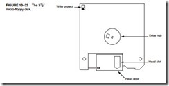
The 3 1/2 " Micro-Floppy Disk. A popular disk size is the 31/2" micro-floppy disk. Recently, this size floppy disk has begun to be replaced by the USB pen drive as the dominant transportable media. The micro-floppy disk is a much improved version of the mini-floppy disk described earlier. Figure 13–22 illustrates the 31/2" micro-floppy disk.
Disk designers noticed several shortcomings of the mini-floppy, which is a scaled down version of the 8" standard floppy, soon after it was released. Probably one of the biggest problems with the mini-floppy is that it is packaged in a semi-rigid plastic cover that bends easily. The micro-floppy is packaged in a rigid plastic jacket that will not bend easily. This provides a much greater degree of protection to the disk inside the jacket.
Another problem with the mini-floppy is the head slot that continually exposes the surface of the disk to contaminants. This problem is also corrected on the micro-floppy because it is constructed with a spring-loaded sliding head door. The head door remains closed until the disk is inserted into the drive. Once inside the drive, the drive mechanism slides open the door, exposing the surface of the disk to the read/write heads. This provides a great deal of protection to the surface of the micro-floppy disk.
Yet another improvement is the sliding plastic write-protection mechanism on the micro- floppy disk. On the mini-floppy disk, a piece of tape was placed over a notch on the side of the jacket to prevent writing. This plastic tape easily became dislodged inside disk drives, causing problems. On the micro-floppy, an integrated plastic slide has replaced the tape write-protection mechanism. To write-protect (prevent writing) the micro-floppy disk, the plastic slide is moved to open the hole through the disk jacket. This allows light to strike a sensor that inhibits writing.
Still another improvement is the replacement of the index hole with a different drive mechanism. The drive mechanism on the mini-floppy allows the disk drive to grab the disk at any point. This requires an index hole so that the electronics can find the beginning of a track. The index hole is another trouble spot because it collects dirt and dust. The micro-floppy has a drive mechanism that is keyed so that it only fits one way inside the disk drive. The index hole is no longer required because of this keyed drive mechanism. Because of the sliding head mechanism and the fact that no index hole exists, the micro-floppy disk has no place to catch dust or dirt.
Two types of micro-floppy disks are widely available: the double-sided, double-density (DSDD) and the high-density (HD). The double-sided, double-density micro-floppy disk has 80 tracks per side, with each track containing nine sectors. Each sector contains 512 bytes of information. This allows 80 tracks per side × 2 sides × 9 sectors × 512 bytes per sector, or 737,280 (720K) bytes of data to be stored on a double-density, double-sided floppy disk.
The high-density, double-sided micro-floppy disk stores even more information. The high- density version has 80 tracks per side, but the number of sectors is doubled to 18 per track. This format still uses 512 bytes per sector, as did the double-density format. The total number of bytes on a high-density, double-sided micro-floppy disk is 80 tracks per side × 2 sides × 18 sectors per track × 512 bytes per sector, or 1,474,560 (1.44M) bytes of information.
Pen Drives
Pen drives, or flash drives, as they are often called, are replacements for floppy disk drives that use flash memory to store data. A driver, which is part of Windows (except for Windows 98), treats the pen drive as a floppy with tracks and sectors even though it really does not contain tracks and sectors. As with a floppy, the FAT system is used for the file structure. The memory in this type of drive is serial memory. When a pen drive is connected to the USB bus, the operating system recognizes it and allows data to be transferred between it and the computer.
Newer pen drives use the USB 2.0 bus specification to transfer data at a much higher rate of speed than the older USB 1.1 specification. Transfer speeds for USB 1.1 are a read speed of 750 KBps and a write speed of 450 KBps. The USB 2.0 pen drives have a transfer speed of about 48 MBps. The pen drive is currently available in sizes up to 4G bytes and has an erase cycle of up to 1,000,000 erases. The price is very reasonable when compared to the floppy disk.
Hard Disk Memory
Larger disk memory is available in the form of the hard disk drive. The hard disk drive is often called a fixed disk because it is not removable like the floppy disk. A hard disk is also often called a rigid disk. The term Winchester drive is also used to describe a hard disk drive, but less commonly today. Hard disk memory has a much larger capacity than the floppy disk memory. Hard disk memory is available in sizes approaching 1 T (tera) bytes of data. Common, low-cost (less than $1 per gigabyte) sizes are presently 20G bytes to 500G bytes.
There are several differences between the floppy disk and the hard disk memory. The hard disk memory uses a flying head to store and read data from the surface of the disk. A flying head, which is very small and light, does not touch the surface of the disk. It flies above the surface on a film of air that is carried with the surface of the disk as it spins. The hard disk typically spins at 3000 to 15,000 RPM, which is many times faster than the floppy disk. This higher rotational speed allows the head to fly (just as an airplane flies) just over the top of the surface of the disk. This is an important feature because there is no wear on the hard disk’s surface, as there is with the floppy disk.
Problems can arise because of flying heads. One problem is a head crash. If the power is abruptly interrupted or the hard disk drive is jarred, the head can crash onto the disk surface, which can damage the disk surface or the head. To help prevent crashes, some drive manufacturers have included a system that automatically parks the head when power is interrupted. This type of disk drive has auto-parking heads. When the heads are parked, they are moved to a safe landing zone (unused track) when the power is disconnected. Some drives are not auto-parking; they usually require a program that parks the heads on the innermost track before power is dis- connected. The innermost track is a safe landing area because it is the very last track filled by the disk drive. Parking is the responsibility of the operator in this type of disk drive.
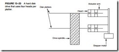
Another difference between a floppy disk drive and a hard disk drive is the number of heads and disk surfaces. A floppy disk drive has two heads, one for the upper surface and one for the lower surface. The hard disk drive may have up to eight disk surfaces (four platters), with up to two heads per surface. Each time that a new cylinder is obtained by moving the head assembly, 16 new tracks are available under the heads. See Figure 13–23, which illustrates a hard disk system.
Heads are moved from track to track by using either a stepper motor or a voice coil. The stepper motor is slow and noisy, while the voice coil mechanism is quiet and quick. Moving the head assembly requires one step per cylinder in a system that uses a stepper motor to position the heads. In a system that uses a voice coil, the heads can be moved many cylinders with one sweeping motion. This makes the disk drive faster when seeking new cylinders.
Another advantage of the voice coil system is that a servo mechanism can monitor the amplitude of the signal as it comes from the read head and make slight adjustments in the position of the heads. This is not possible with a stepper motor, which relies strictly on mechanics to position the head. Stepper-motor-type head positioning mechanisms can often become misaligned with use, while the voice coil mechanism corrects for any misalignment.
Hard disk drives often store information in sectors that are 512 bytes long. Data are addressed in clusters of eight or more sectors, which contain 4096 bytes (or more) on most hard disk drives. Hard disk drives use either MFM or RLL to store information. MFM is described with floppy disk drives. Run-length limited (RLL) is described here.
A typical older MFM hard disk drive uses 18 sectors per track so that 18 K bytes of data are stored per track. If a hard disk drive has a capacity of 40M bytes, it contains approximately 2280 tracks. If the disk drive has two heads, this means that it contains 1140 cylinders; if it contains four heads, then it has 570 cylinders. These specifications vary from disk drive to disk drive.
RLL Storage. Run-length limited (RLL) disk drives use a different method for encoding the data than MFM. The term RLL means that the run of zeros (zeros in a row) is limited. A common RLL encoding scheme in use today is RLL 2,7. This means that the run of zeros is always between two and seven. Table 13–3 illustrates the coding used with standard RLL.
Data are first encoded by using Table 13–3 before being sent to the drive electronics for storage on the disk surface. Because of this encoding technique, it is possible to achieve a 50% increase in data storage on a disk drive when compared to MFM. The main difference is that the RLL drive often contains 27 tracks instead of the 18 found on the MFM drive. (Some RLL drives also use 35 sectors per track.)
In most cases, RLL encoding requires no change to the drive electronics or surface of the disk. The only difference is a slight decrease in the pulse width using RLL, which may require slightly finer oxide particles on the surface of the disk. Disk manufacturers test the surface of the disk and grade the disk drive as either an MFM-certified or an RLL-certified drive. Other than grading, there is no difference in the construction of the disk drive or the magnetic material that coats the surface of the disks.
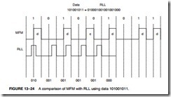
Figure 13–24 shows a comparison of MFM data and RLL data. Notice that the amount of time (space) required to store RLL data is reduced when compared to MFM. Here 101001011 is coded in both MFM and RLL so that these two standards can be compared. Notice that the width
of the RLL signal has been reduced so that three pulses fit in the same space as a clock and a data pulse for MFM. A 40M-byte MFM disk can hold 60M bytes of RLL-encoded data. Besides holding more information, the RLL drive can be written and read at a higher rate.
All hard disk drives use today RLL encoding. There are a number of disk drive interfaces in use today. The oldest is the ST-506 interface, which uses either MFM or RLL data. A disk sys- tem using this interface is also called either MFM or RLL disk system. Newer standards are also found in use today, which include ESDI, SCSI, and IDE. All of these newer standards use RLL, even though they normally do not call attention to it. The main difference is the interface between the computer and the disk drive. The IDE system is becoming the standard hard disk memory interface.
The enhanced small disk interface (ESDI) system, which has disappeared, is capable of transferring data between itself and the computer at rates approaching 10M bytes per second. An ST-506 interface can approach a transfer rate of 860K bytes per second.
The small computer system interface (SCSI) system is also in use because it allows up to seven different disk or other interfaces to be connected to the computer through same interface controller. SCSI is found in some PC-type computers and also in the Apple Macintosh system. An improved version, SCSI-II, has started to appear in some systems. In the future, this interface may be replaced with IDE in most applications.
Today one of the most common systems is the integrated drive electronics (IDE) system, which incorporates the disk controller in the disk drive and attaches the disk drive to the host sys- tem through a small interface cable. This allows many disk drives to be connected to a system without worrying about bus conflicts or controller conflicts. IDE drives are found in newer IBM PS-2 systems and many clones. Even Apple computer systems are starting to be found with IDE drives in place of the SCSI drives found in older Apple computers. The IDE interface is also capable of driving other I/O devices besides the hard disk. This interface also usually contains at least a 256K- to 8M-byte cache memory for disk data. The cache speeds disk transfers. Common access times for an IDE drive are often less than 8 ms, whereas the access time for a floppy-disk is about 200 ms.
Sometimes IDE is also called ATA. ATA is an acronym for AT attachment where the AT means the Advanced Technology computer. The latest system is the serial ATA interface or SATA. This interface transfers serial data at rates of 150 MBps (or 300 MBps for SATA2), which is faster than any IDE interface. Not yet released is SATA3, which transfers data at a rate of 600 MBps. The transfer rate is higher because the logic 1 level is no longer 5.0 V. In the SATA interface, the logic 1 level is 0.5 V, which allows data to be transferred at higher rates because it takes less time for the signal to rise to 0.5 V than it takes to rise to 5.0 V. Speeds of this interface should eventually reach 600 MBps with SATA3.
Optical Disk Memory
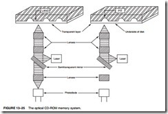
Optical disk memory (see Figure 13–25) is commonly available in two forms: the CD-ROM (compact disk/read only memory) and the WORM (write once/read mostly). The CD-ROM is the lowest cost optical disk, but it suffers from lack of speed. Access times for a CD-ROM are typically 300 ms or longer, about the same as a floppy disk. (Note that slower CD-ROM devices are on the market and should be avoided.) Hard disk magnetic memory can have access times as little as 11 ms. A CD-ROM stores 660M bytes of data, or a combination of data and musical pas- sages. As systems develop and become more visually active, the use of the CD-ROM drive will become even more common.
The WORM drive sees far more commercial application than the CD-ROM. The problem is that its application is very specialized due to the nature of the WORM. Because data may be written only once, the main application is in the banking industry, insurance industry, and other massive data-storing organizations. The WORM is normally used to form an audit trail of trans- actions that are spooled onto the WORM and retrieved only during an audit. You might call the WORM an archiving device.
Many WORM and read/write optical disk memory systems are interfaced to the microprocessor by using the SCSI or ESDI interface standards used with hard disk memory. The difference is
that the current optical disk drives are no faster than the most floppy drives. Some CD-ROM drives are interfaced to the microprocessor through proprietary interfaces that are not compatible with other disk drives.
The main advantage of the optical disk is its durability. Because a solid-state laser beam is used to read the data from the disk, and the focus point is below a protective plastic coating, the surface of the disk may contain small scratches and dirt particles and still be read correctly. This feature allows less care of the optical disk than a comparable floppy disk. About the only way to destroy data on an optical disk is to break it or deeply scar it.
The read/write CD-ROM drive is here and its cost is dropping rapidly. In the near future, we should start seeing the read/write CD-ROM replacing floppy disk drives. The main advantage is the vast storage available on the read/write CD-ROM. Soon, the format will change so that many G bytes of data will be available. The new versatile read/write CD-ROM, called a DVD, became available in late 1996 or early 1997. The DVD functions exactly like the CD-ROM except that the bit density is much higher. The CD-ROM stores 660M bytes of data, while the current-genre DVD stores 4.7G bytes or 9.4G bytes, depending on the current standard. Look for the DVD to eventually replace the CD-ROM format completely, at least for computer data storage, but maybe not for audio.
New to this technology are the Blu-ray DVD from Sony Corporation and the HD-DVD from Toshiba Corporation. The Blu-ray DVD has a capacity of 50 GB and the HD-DVD has a capacity of 30 GB. Which format will eventually become the standard is conjecture. The main advantage is to video, where high-resolution HD video (1080p) can be stored on either Blu-ray or HD-DVD. Because there are rumors of a higher resolution video standard in the future, even Blu-ray and HD-DVD may be replaced by some other technology. The big change from older DVDs and the newer technology is a switch from a red laser to a blue laser. A blue laser has a higher frequency, which means that it can read more information per second from the DVD, hence a high storage density.
