USING THE KEYBOARD AND VIDEO DISPLAY
Today, there are few programs that don’t use the keyboard and video display. This section of the text explains how to use the keyboard and video display connected to the IBM PC or any compatible computer running under Windows.
Reading the Keyboard
The keyboard of the personal computer is read by many different objects available to Visual C++. Data read from the keyboard are either in ASCII-coded or in extended ASCII-coded form. They are then either stored in 8-bit ASCII form or in 16-bit Unicode form. As mentioned in an earlier chapter, Unicode contains ASCII code in the codes 0000H–00FFH. The remaining codes are used for foreign language character sets. Do not use cin or getch to read keys in Visual C++ as we do in a DOS C++ console application; in place of cin or getch we use controls in Visual C++ that accomplish the same task.
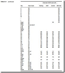
The ASCII-coded data appear as outlined in Table 1–8 in Section 1–4. The extended character set of Table 1–9 applies to printed or displayed data only, and not to keyboard data. Notice that the ASCII codes in Table 1–8 correspond to most of the keys on the keyboard. Also available through the keyboard are extended ASCII-coded keyboard data. Table 8–1 lists most of the extended ASCII codes obtained with various keys and key combinations. Notice that most keys on the keyboard have alternative key codes. Each function key has four sets of codes selected by the function key alone, the Shift-function key combination, the alternate-function key combination, and the Control-function key combination.
Creating a Visual C++ Express application that contains a simple textbox gives a better understanding of reading a key in Windows. Figure 8–1 shows such an application written as a forms-based application. Recall that to create a forms-based application:
1. Start Visual C++ Express.
2. Click on Create: Project.
3. Select a CLR Windows Forms Application, then give it a name and click on OK.
Once the new forms-based application is created, select the textbox control from the tool- box and draw it on the screen of the dialog box, as illustrated in Figure 8–1.
Setting Focus. The first thing that should be added to the application is a set focus to the textbox control. When focus is set, the cursor moves to the object, in this case the textbox. Focus is set to a control by using textBox1->Focus(), which in our case is because the textbox control is named textBox1. This statement is placed in the Form1_Load function, which must be installed by double-clicking on a blank area of the form. The Form1_Load function can also be installed by clicking on the yellow lightning bolt and selecting Load and then adding it by double- clicking on the blank textbox to its right. The application will now set focus to the textbox1 control when started. This means that the blinking cursor appears inside the textbox control.
When the application is executed and keys are typed into the textbox control, the program reads the keyboard and displays each character as it is typed. In some cases this may be undesirable and may require some filtering. One such case is if the program requires that the user enter only hexadecimal data. In order to intercept keystrokes as they are typed, the event handlers
KeyDown and KeyPress are used for the textbox. The KeyDown event handler is called when the key is pressed down, which is followed by a call to the KeyPress event handler. To insert these functions into the application for the textbox control, click on the textbox and then select the Properties window. Next find the yellow lightning bolt and click on it, and install KeyDown and KeyPress events handlers for the textbox1 control.
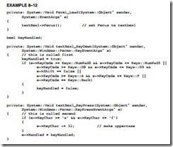
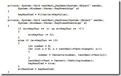
To illustrate filtering, this application uses the KeyDown function to look at each keyboard character that is typed before the program uses the keystroke. This allows the characters to be modified. Here the program only allows the numbers 0 through 9 and the letters A through F to be typed from the keyboard. If a lowercase letter is typed, it is converted into uppercase. If any other key is typed, it is ignored.
To accomplish filtering, use the KeyEventArg sˆ class argument e, which is passed to the KeyDown functon as illustrated in Example 8–12. In this example, C++ is used to accomplish the task of filtering the keyboard entry into the textbox control. The variable keyHandled is used to indicate whether or not the key is handled by the filtering. If keyHandled is set to false, the key has not been han- dled and it will appear in the textbox. Likewise, if keyhandled is set to true, the key has been handled and will not appear in the textbox. The condition of keyHandled is passed to Windows in the KeyPress event that also appears in Example 8–12. Note that Keys::D0 through Keys::D9 are the number keys on the QWERTY keyboard and Keys::NumPad0 through Keys::NumPad9 are on the numeric keypad. A D8 with the shift equal to false is the eight key and a D8 with shift equal to true is an asterisk key.
The if statement in KeyPress event tests the e->KeyCode value for the letters a, b, c d, e, and f, which can be either uppercase or lowercase. The KeyDown event tests for the numbers 0–9 on both the keyboard and the number pad. Also the backspace key is tested. If any of these are typed, keyHandled is set to false to indicate that these keys are not handled by the KeyDown function. The KeyPress event determines if the letter a–f is typed and converts it into uppercase by subtracting 32. The 32 is the bias between uppercase and lowercase letters in the ASCII code.
Next, a return with e->Handled set into true or false occurs. A return true causes Windows to dis- pose of the keystroke. In this case, if a number is typed, or the letters a through f or A through F, the keystroke is passed to Windows framework by the normal return false at the end of the KeyPress function. This filters the keystrokes so only A–F or 0–9 appears in the edit box.
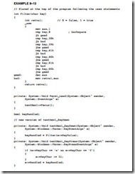
Example 8–12 is repeated using the inline assembler to accomplish the same task in Example 8–13. Here a function, called filter, returns a true or false that is passed to keyHandled in the KeyDown function. In this example, C++ seems to require less typing than assembly language, but it is important to be able to visualize both forms. Don’t forget to change the project property, Common Language Runtime Support to /CLR, so this will function correctly (see Chapter 7). Notice that KeyValue is used with the assembly version to pass a char to the Filter function. Also note that an integer return value of 0 is false and 1 is true.
If this code is added to the application and executed, the only keys that will appear in the textbox control are 0–9 and A–F. Any amount of filtering can be done in a likewise manner in the Visual C++ Express environment. The properties of the textbox control include character casing, which could have been set to uppercase to shorten the filtering task, but here software accomplished the uppercase feature.
Using the Video Display
As with the keyboard, in Visual C++ objects are used to display information. The textbox control can be used to either read data or display data as can most objects. Modify the application pre- sented in Figure 8–1 so it contains an additional textbox control as shown in Figure 8–2. Notice that a few label controls have been added to the form to identify the contents of the textbox con- trols. In this new application the keyboard data is still read into textbox control textBox1, but when the Enter key is typed, a decimal version of the data entered into textBox1 appears in textBox2—the second textbox control. Make sure that the second control is named textBox2 to maintain compatibility with the software presented here.
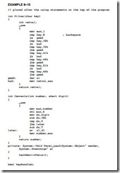
To cause the program to react to the Enter key, ASCII code 13 (0DH or 0x0d), modify the KeyPress function of Example 8–13 as shown in Example 8–14. Notice how the Enter key is detected using an else if. Once the Enter key is detected, the contents of textBox1 are converted to decimal for display in textBox2, as shown in Example 8–15.
A slight problem arises with textbox data; the data entered into a textbox control is accessed as a string, but not as a hexadecimal number. In this example program (see Example 8–15), a function called Converts changes the hexadecimal character string into a number. The program now has two functions that contain assembly code.
Example 8–15 shows the completed application. When the Enter key is pressed, the pro- gram obtains the character string from textBox1 and converts it, a character at a time, into an integer using the Converts function. Once an integer is created, it is changed into a character string using the Convert class and its member function ToString for display in textBox2.
The assembly language in the Converts function converts from ASCII to binary by subtracting 30h from each digit. This action converts ASCII numbers (0–9) 30H through 39H to the binary numbers 0 through 9. It does not convert the letters 41H through 46H (A through F) to binary because the result is 11H through 16H and not 0AH through 0FH. To adjust the values obtained for the letters, use a cmp (compare) instruction to detect 11H through 16H and then subtract an additional 7 to convert from 11H through 16H to 0AH to 0FH. Once the ASCII digit is in binary form, the integer at number is shifted left four binary places and the binary version of the ASCII digit is ORed to it to accumulate the converted digits in temp1.
Once the hexadecimal number from textBox1 is converted to binary in variable number, it is displayed in textBox2 using the ToString function in the Convert class. As before, a return true informs the Windows interface that the Enter key has been processed by the program. If a return false is used in KeyPress for the Enter key, the computer generates an error beep.
Using a Timer in a Program
Timers are important in programming. A timer is programmed to fire or trigger after a known amount of time, which is given in milliseconds. The allowable range for the timer is from 1 to 2G milliseconds. This allows a timer to be programmed for just about any time needed. If programmed with 1000, the timer fires in 1 second, and if programmed with 60000, the timer fires in 1 minute and so forth. A timer may be used a single time or multiple times and as many timers as needed (up to 2 billion) may appear in a program. The timer is found in the toolbox at the Design window.
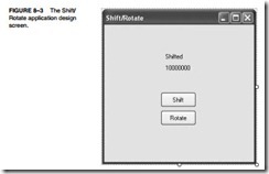
To illustrate the timer and its use in a program, a design appears in Figure 8–3 that allows a user to demonstrate a shift or a rotate on a binary number. The shift or rotate is animated with the timer in this program. The design contains two label controls and two button controls plus the timer control. Add all five of these controls to the application. The timer does not appear on the form, but in an area near the bottom of the design screen. Notice that a few properties of the form are changed so the icon is not shown and the Text property of the form is changed to Shift/Rotate instead of Form1. Also the Text properties of the labels and buttons are changed as indicated.
Once the form appears as shown in Figure 8–3, add event handler functions ( yellow light- ning bolt) for the two command buttons (Click) and for the timer (Tick). To add an event handler, click on the button or timer, go to the Properties window at the right of the screen, and click on the yellow lightning bolt and select the event. The program contains three handlers, two for but- ton clicks and one for a timer tick.
At the design screen go to the properties of the timer and set the interval to 500, which is 1⁄2 second. Do not enable the timer. The timer is enabled in the software when a button is clicked to either rotate a number or shift a number in 1⁄2-second animation steps.
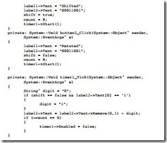
Example 8–16 illustrates the software added to the application in the three handlers required to implement the application for Figure 8–3. The software for the two button click han- dlers is nearly identical except for the Boolean variable shift. The two statements in each place text onto the labels. If the shift button is pressed, “Shifted” is displayed, and if the rotate button is pressed, “Rotated” is displayed on label1. The second label has the test number 00011001 dis- played. The Boolean variable shift is set to true for the shift button and false for the rotate button. In both button handlers, count is set to 8 to shift or rotate the number 8 places. Finally, the last statement in each button handler starts the timer. As an alternative, the enabled member could be set to true to start the timer. Once the timer is started or enabled, it fires in 1⁄2 second and calls the Tick handler for timer1 where all the work is accomplished in this program.
The first statement in the timer tick function sets the digit string to zero. This is the number that shifts into the right end of label2. For a shift, it will remain a zero and for a rotate it depends on the leftmost digit of the number in label2. If shift is false (rotate) and the leftmost digit of label2 is 1, the digit is changed to 1. After the if statement, the number is shifted or rotated and placed on label2. If the count reaches 0, after 8 iterations in 4 seconds, the timer is disabled by setting the enabled member to false to stop the animation.
This application is embellished by adding a pair of radio buttons to select right and left for the direction of the shift or rotate. Label2 can also be replaced with a textbox so the user could enter any binary number (with appropriate filtering) and shift or rotate it left or right.
The program does not use any assembly language, but if a breakpoint is inserted in the timer function, the assembly code can be viewed in Visual C++ Express. When the program Breaks, go to the Debug menu and select Windows. Next, select the Disassembly window to show the assembly language for the timer tick function.
The Mouse
The mouse pointing device, as well as a track ball, is accessed from within the framework of Visual C++ Express. Like many other devices under the control of Windows, the mouse can have message handlers installed in an application so that mouse movement and other functions can be used in a program. As we saw in prior examples, message handlers (event handlers) are installed in an application in the Properties section by clicking on the icon to the right of the lightning bolt. The mouse handlers are listed in Table 8–2.
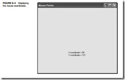
For an illustration of how to use the mouse, refer to the example application presented in Figure 8–4. This example shows the mouse pointer coordinates as the pointer is moved within
the dialog application. Although the software listing (see Example 8–17) does not use any assembly language, it does illustrate how to obtain and display the position of the mouse pointer. Notice how the MouseEventArgsˆ are used to obtain the location of the mouse pointer using the X and Y coordinates.
Example 8–17 illustrates the only part of the application that is modified to display the mouse coordinates. The MouseMove function is installed when the MouseMove event handler is installed in the program. This application uses two labels to display the mouse coordinates. These two objects are named label1 and label2 for the application. The MouseMove function returns the position of the mouse pointer in the Location data structure as members X and Y. This example uses the Convert class to convert the integer returned as the mouse point X or Y into an ASCII character string for placement on a label.
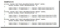
The mouse pointer does not track through the two labels in the application. In order to have the application display the coordinates in the labels as well as the form, two additional MouseMove handlers must be installed for the labels. Example 8–18 shows the addition of two more MouseMove functions and biases added to the X and Y coordinates so the mouse tracks through the labels. Where are the bias numbers obtained? The biases are in the Location proper- ties of each label where the label position is given as X, Y. The numbers in the application will depend on where the labels are placed on the form and could be obtained by using label1->Location.X and so forth.
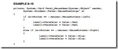
Install a mouse handler for the Mouse Down event. Modify the application by adding the Mouse Down event handler as illustrated in Example 8–19. The function causes the left button to change the color of the labels to red when clicked and the right button changes the color of the labels to blue when pushed. The color codes used with most functions in Visual C++ are found in the Color class for most common colors. The application tests for the left and right mouse but- tons using the Button member of the Mouse Event Args object as shown. (Microsoft chose the name mouses for the Mouse Buttons enumerator.)

