DATA CONVERSIONS
In computer systems, data are seldom in the correct form. One main task of the system is to convert data from one form to another. This section of the chapter describes conversions between binary and ASCII data. Binary data are removed from a register or memory and converted to ASCII for the video display. In many cases, ASCII data are converted to binary as they are typed on the keyboard. We also explain converting between ASCII and hexadecimal data.
Converting from Binary to ASCII
Conversion from binary to ASCII is accomplished in three ways: (1) by the AAM instruction if the number is less than 100 (provided the 64-bit extensions are not used for the conversion), (2) by a series of decimal divisions (divide by 10), or (3) by using the C++ Convert class function ToString. Techniques 1 and 2 are presented in this section.
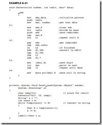
The AAM instruction converts the value in AX into a two-digit unpacked BCD number in AX. If the number in AX is 0062H (98 decimal) before AAM executes, AX contains 0908H after AAM executes. This is not ASCII code, but it is converted to ASCII code by adding 3030H to AX. Example 8–20 illustrates a program that uses the procedure that processes the binary value in AL (0–99) and displays it on the video screen as a decimal number. The procedure blanks a leading zero, which occurs for the numbers 0–9, with an ASCII space code. This example pro- gram displays the number 74 (testdata) on the video screen. To implement this program, create a forms-based application in Visual C++ and place a single label called label1 on the form. The number 74 will appear if the assembly language function in Example 8–20 is placed at the top of the program after the last using statement and the project is changed to a /CLR program. The call to the assembly language function is placed in the Load event handler for the form.
The reason that AAM converts any number between 0 and 99 to a two-digit unpacked BCD number is because it divides AX by 10. The result is left in AX so AH contains the quotient and AL the remainder. This same scheme of dividing by 10 can be expanded to convert any whole number of any number system (if the divide-by number is changed) from binary to an ASCII-coded character string that can be displayed on the video screen. For example, if AX is divided by 8 instead of 10, the number is displayed in octal.
The algorithm (called Horner’s algorithm) for converting from binary to decimal ASCII code is:
1. Divide by 10, then save the remainder on the stack as a significant BCD digit.
2. Repeat step 1 until the quotient is a 0.
3. Retrieve each remainder and add 30H to convert to ASCII before displaying or printing.
Example 8–21 shows how the unsigned 32-bit number is converted to ASCII and displayed on the video screen. Here, we divide EAX by 10 (for decimal) and save the remainder on the stack after each division for later conversion to ASCII. After all the digits have been converted, the result is displayed on the video screen by removing the remainders from the stack and converting them to ASCII code. This program also blanks any leading zeros that occur. As mentioned, any number base can be used by changing the radix variable in this example. Again, to implement this example create a forms application with the /CLR option and a single label called label1. If the number base is greater than 10, letters are used for the representation of characters beyond 9. The software functions from base 2 to base 36.
Converting from ASCII to Binary
Conversions from ASCII to binary usually start with keyboard entry. If a single key is typed, the conversion occurs when 30H is subtracted from the number. If more than one key is typed, conversion from ASCII to binary still requires 30H to be subtracted, but there is one additional step. After subtracting 30H, the number is added to the result after the prior result is first multiplied by 10.
The algorithm for converting from ASCII to binary is:
1. Begin with a binary result of 0.
2. Subtract 30H from the character to convert it to BCD.
3. Multiply the result by 10, and then add the new BCD digit.
4. Repeat steps 2 and 3 for each character of the number.
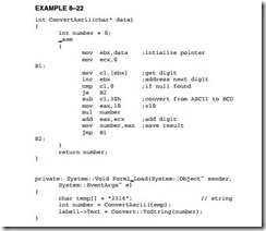
Example 8–22 illustrates a program that implements this algorithm. Here, the binary number is displayed from variable temp on label1 using the Convert class to convert it to a string. Each time this program executes, it reads a number from the char variable array numb and converts it to binary for display on the label.
Displaying and Reading Hexadecimal Data
Hexadecimal data are easier to read from the keyboard and display than decimal data. These types of data are not used at the application level, but at the system level. System-level data are often hexadecimal, and must either be displayed in hexadecimal form or read from the keyboard as hexadecimal data.
Reading Hexadecimal Data. Hexadecimal data appear as 0 to 9 and A to F. The ASCII codes obtained from the keyboard for hexadecimal data are 30H to 39H for the numbers 0 through 9, and 41H to 46H (A–F) or 61H to 66H (a–f) for the letters. To be useful, a pro- gram that reads hexadecimal data must be able to accept both lowercase and uppercase letters as well as numbers.
Example 8–23 shows two functions: One (Conv) converts the contents of an unsigned char from ASCII code to a single hexadecimal digit, and the other (Readh) converts a String with up to eight hexadecimal digits into a numeric value that is returned as a 32-bit unsigned integer. This example illustrates a balanced mixture of C++ and assembly language to perform the conversion.
Displaying Hexadecimal Data. To display hexadecimal data, a number must be divided into 2-, 4-, or 8-bit sections that are converted into hexadecimal digits. Conversion is accomplished by adding 30H to the numbers 0 to 9 or 37H to the letters A to F for each section.
A function (Disph) stores a string of the contents of the unsigned integer parameter passed to the function. This function converts the unsigned into a two-, four-, or eight-digit character string as selected by parameter size. The function is listed in Example 8–24. Disph(number, 2) converts an unsigned integer number into a two-digit hexadecimal String, where Disph(number, 4) converts it to a four-digit hexadecimal string and Disph(number, 8) converts to an eight-digit hexadecimal character string.
Using Lookup Tables for Data Conversions
Lookup tables are often used to convert data from one form to another. A lookup table is formed in the memory as a list of data that is referenced by a procedure to perform conversions. In many lookup tables, the XLAT instruction is often used to look up data in a table, provided that the table contains 8-bit-wide data and its length is less than or equal to 256 bytes.
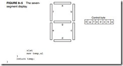
Converting from BCD to Seven-Segment Code. One simple application that uses a lookup table is BCD to seven-segment code conversion. Example 8–25 illustrates a lookup table that contains the seven-segment codes for the numbers 0 to 9. These codes are used with the seven-segment display pictured in Figure 8–5. This seven-segment display uses active high (logic 1) inputs to light a segment. The lookup table code (array temp1) is arranged so that the a segment is in bit position 0 and the g segment is in bit position 6. Bit position 7 is 0 in this example, but it can be used for displaying a decimal point, if required.
The Look Up function, which performs the conversion, contains only a few instructions and assumes that the temp parameter contains the BCD digit (0–9) to be converted to seven- segment code that is returned as an unsigned char. The first instruction addresses the lookup table by loading its address into EBX, and the others perform the conversion and return the seven- segment code as an unsigned char. Here the temp1 array is indexed by the BCD passed to the function in temp.
Using a Lookup Table to Access ASCII Data. Some programming techniques require that numeric codes be converted to ASCII character strings. For example, suppose that you need to display the days of the week for a calendar program. Because the number of ASCII characters in each day is different, some type of lookup table must be used to reference the ASCII-coded days of the week.
The program in Example 8–26 shows a table, formed as an array, which references ASCII-coded character strings. Each character string contains an ASCII-coded day of the week. The table contains references to each day of the week. The function that accesses the day of the week uses the day parameter, with the numbers 0 to 6 to refer to Sunday through Saturday. If day contains a 2 when this function is invoked, the word Tuesday is displayed on the video screen. Please note that this function does not use any assembly code, since we are merely accessing an element in an array using the day of the week as an index. It is shown so additional uses for arrays can be presented, because they may have application in programs used with embedded microprocessors.
An Example Program Using a Lookup Table
Figure 8–6 shows the screen of a dialog application called Display that displays the a seven- segment-style character on the screen for each numeric key typed on the keyboard. As we learned in prior examples, the keyboard can be intercepted in a Visual C++ program using the Key Down and Key Press handler functions, which is exactly what the program does to obtain the key from the keyboard. Next the code typed is filtered so only 0–9 are accepted and a lookup table is used to access the seven-segment code for display.
The display digit is drawn using panel control objects. The horizontal bars are drawn using dimensions 120 × 25 and the vertical bars are drawn using dimensions 25 × 75. The dimensions of an object appear in the extreme lower right corner of the resource screen in Visual Studio. Make sure that you add the panels in the same order as the display; that is, add label a first, followed by b, and so on, just as in the seven-segment display of Figure 8–5. Use panel1 through panel7 for the variable names of the panels in this application and don’t forget to select a back- ground color of black.
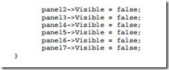
Add the function listed in Example 8–27 called Clear to the program to clear the display. This is used to clear the digit from the screen when the program first executes and also before a new digit is displayed. Notice that the Visible property of the panels is used to hide the digit. An alternate method changes the color of the panel.
Once a key is typed, the Key Down function (see Example 8–28) filters the keystroke and converts the keystroke into seven-segment code using the lookup table. After converting to seven-segment code, the Show Digit function is called to show the digit on the screen. The Show Digit function tests each bit of the seven-segment code and changes the visibility of each panel to display a digit. This program does not use any assembly code for its operation.


